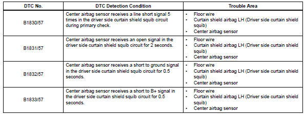
Toyota RAV4 (XA40) 2013-2018 Service Manual: Short in driver side curtain shield squib circuit
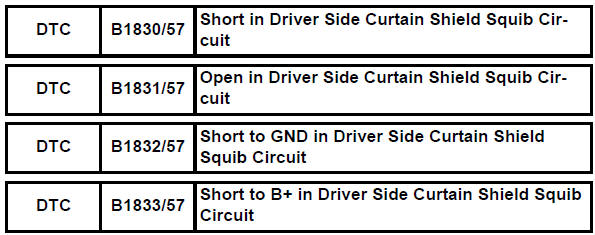
Description
The driver side curtain shield squib circuit consists of the center airbag sensor and the curtain shield airbag lh.
The circuit instructs the srs to deploy when the deployment conditions are met.
These dtcs are recorded when a malfunction is detected in the driver side curtain shield squib circuit.
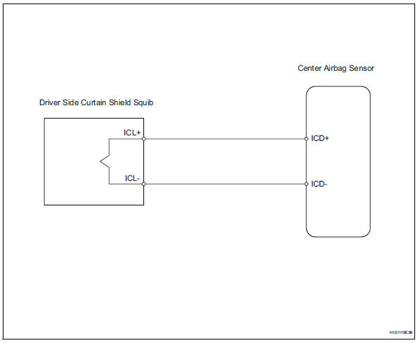
Wiring diagram
Inspection procedure
Hint:
- Perform the simulation method by selecting the "check mode" (signal check) with the intelligent tester (see page rs-49).
- After selecting the "check mode" (signal check), perform the simulation method by wiggling each connector of the airbag system or driving the vehicle on a city or rough road (see page rs-49).
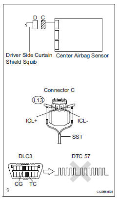
- Check curtain shield airbag assembly lh (driver side curtain shield squib)
- Turn the ignition switch off.
- Disconnect the cable from the negative (-) battery terminal, and wait for at least 90 seconds.
- Disconnect the connector from the curtain shield airbag lh.
- Connect the white wire side of sst (resistance 2.1 Ù) to connector c.
Caution:
Never connect a tester to the curtain shield airbag lh (driver side curtain shield squib) for measurement, as this may lead to a serious injury due to airbag deployment.
Notice:
- Do not forcibly insert sst into the terminals of the connector when connecting.
- Insert sst straight into the terminals of the connector.
Sst 09843-18060
- Connect the cable to the negative (-) battery terminal, and wait for at least 2 seconds.
- Turn the ignition switch on, and wait for at least 60 seconds.
- Clear the dtcs (see page rs-49).
- Turn the ignition switch off.
- Turn the ignition switch on, and wait for at least 60 seconds.
- Check the dtcs (see page rs-49).
Ok: dtc b1830, b1831, b1832, b1833 or 57 is not output.
Hint:
Dtcs other than dtc b1830, b1831, b1832, b1833 or 57 may be output at this time, but they are not related to this check.

- Check connector
- Turn the ignition switch off.
- Disconnect the cable from the negative (-) battery terminal, and wait for at least 90 seconds.
- Disconnect sst from connector c.
- Check that the floor wire connector (on the curtain shield lh side) is not damaged.
Ok: lock button is not disengaged, and claw of lock is not deformed or damaged.


- Check floor wire (driver side curtain shield squib circuit)
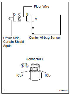
- Disconnect the connector from the center airbag sensor.
- Connect the cable to the negative (-) battery terminal, and wait for at least 2 seconds.
- Turn the ignition switch on.
- measure the voltage of the wire harness side connector.
Standard voltage 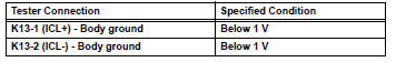
- Turn the ignition switch off.
- Disconnect the cable from the negative (-) battery terminal, and wait for at least 90 seconds.
- Measure the resistance of the wire harness side connector
Standard resistance 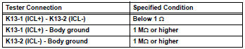
- Release the activation prevention mechanism built into connector b (see page rs-37).
- Measure the resistance of the wire harness side connector.
Standard resistance 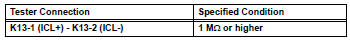

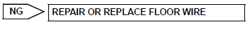
Replace center airbag sensor assembly
 Short in front passenger side - side squib circuit
Description
The front passenger side - side squib circuit consists of the center airbag
sensor and the front seat side
airbag rh.
The circuit instructs the srs to deploy when the deployment ...
 Short in front passenger side curtain shield squib circuit
Description
The front passenger side curtain shield squib circuit consists of the center
airbag sensor and the curtain
shield airbag rh.
The circuit instructs the srs to deploy when the dep ...
Other materials:
Shift solenoid "d" control circuit
Description
Shifting from 1st to o/d is performed in combination with the on and off
operation of the shift solenoid
valves sl1 and sl2, which are controlled by the ecm. If an open or short circuit
occurs in any of the shift
solenoid valves, the ecm controls the remaining normal shift sol ...
Fail-safe chart
Fail-safe chart
This function minimizes the loss of the ect functions
when a malfunction occurs in a sensor or solenoid.
Automatic transmission fluid (atf) temperature
sensor:
when the atf temperature sensor has a
malfunction, o/d up-shift is prohibited
Counter gear speed sensor n ...
Audio settings
Settings are available for adjusting the radio operation, cover
art, etc.
Screen for audio settings
Press the ÔÇťsetupÔÇŁ button.
Select ÔÇťaudioÔÇŁ on the ÔÇťsetupÔÇŁ screen.
Number of radio presets
select the number of radio
preset stations.
Display cover art on/off
Auto ...
