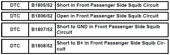
Toyota RAV4 (XA40) 2013-2018 Service Manual: Short in front passenger side squib circuit
Description
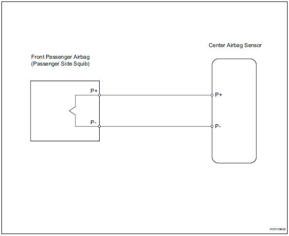
The front passenger side squib circuit consists of the center airbag sensor and the front passenger airbag.
The circuit instructs the srs to deploy when the deployment conditions are met.
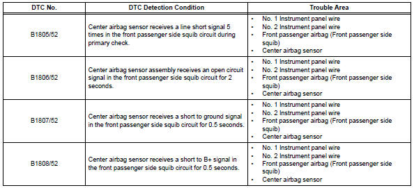
These dtcs are recorded when a malfunction is detected in the front passenger side squib circuit.
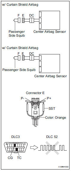
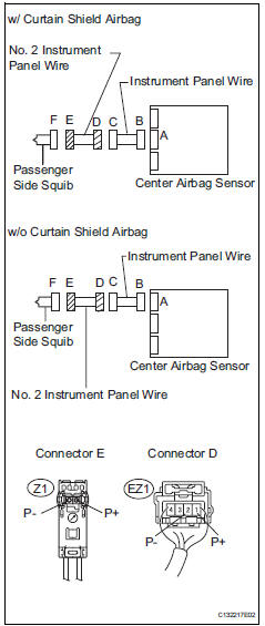
Wiring diagram
Inspection procedure
Hint:
- Perform the simulation method by selecting the "check mode" (signal check) with the intelligent tester (see page rs-52).
- After selecting the "check mode" (signal check), perform the simulation method by wiggling each connector of the airbag system or driving the vehicle on a city or rough road (see page rs-52).
- Check front passenger airbag assembly (front passenger side squib)
- Turn the ignition switch off.
- Disconnect the cable from the negative (-) battery terminal, and wait for at least 90 seconds.
- Disconnect the connectors from the front passenger airbag.
- Connect the white wire side of sst (resistance 2.1 Ù) to the instrument panel wire connector e.
Caution:
Never connect a tester to the front passenger airbag (front passenger side squib) for measurement, as this may lead to a serious injury due to airbag deployment.
Notice:
- Do not forcibly insert sst into the terminals of the connector when connecting.
- Insert sst straight into the terminals of the connector.
Sst 09843-18060
- Connect the cable to the negative (-) battery terminal, and wait for at least 2 seconds.
- Turn the ignition switch on, and wait for at least 60 seconds.
- Clear the dtcs (see page rs-49).
- Turn the ignition switch off.
- Turn the ignition switch on, and wait for at least 60 seconds.
- Check the dtcs (see page rs-49).
Ok: dtc b1805, b1806, b1807, b1808 or 52 is not output.
Hint:
Dtcs other than dtc b1805, b1806, b1807, b1808 or 52 may be output at this time, but they are not related to this check.

- Check connector
- Turn the ignition switch off.
- Disconnect the cable from the negative (-) battery terminal, and wait for at least 90 seconds.
- Disconnect sst from the instrument panel wire.
- Check that the instrument panel wire connectors (on the front passenger side airbag) are not damaged.
Ok: lock button is not disengaged, and claw of lock is not deformed or damaged.

- Check instrument panel wire
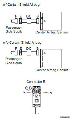
- Disconnect the connector from the center airbag sensor.
- Connect the cable to the negative (-) battery terminal, and wait for at least 2 seconds.
- Turn the ignition switch on.
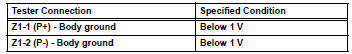
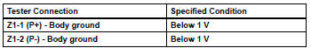
- Measure the voltage of the wire harness side connector.
Standard voltage
- Turn the ignition switch off.
- Disconnect the cable from the negative (-) battery terminal, and wait for at least 90 seconds.
- Measure the resistance of the wire harness side connector.
Standard resistance
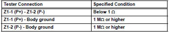
- Release the activation prevention mechanism built into connector b (see page rs-37).
- Measure the resistance of the wire harness side connector.
Standard resistance

- Check no. 2 Instrument panel wire
- Disconnect the no. 2 Floor wire connector from the floor wire.
- Connect the cable to the negative (-) battery terminal, and wait for at least 2 seconds.
- Turn the ignition switch on.
- Measure the voltage of the wire harness side connector.
Standard voltage
- Turn the ignition switch off.
- Disconnect the cable from the negative (-) battery terminal, and wait for at least 90 seconds.
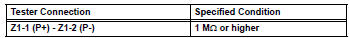
- Measure the resistance of the wire harness side connector.
Standard resistance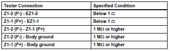

Repair or replace instrument panel wire
 Short in driver side squib circuit
Description
The driver side squib circuit consists of the center airbag sensor, the
spiral cable and the steering pad.
The circuit instructs the srs to deploy when the deployment conditions ...
 Short in driver side squib 2nd step circuit
Description
The driver side squib 2nd step circuit consists of the center airbag sensor,
the spiral cable and the
steering pad.
The circuit instructs the srs to deploy when the deployment c ...
Other materials:
Disassembly
Remove park/neutral position switch assembly
Remove the nut, washer and control shaft lever.
Using a screwdriver, pry off the lock plate.
Remove the nut and lock plate.
Remove the 2 bolts and pull out the switch.
Remove breather plug hose
Remove oil coo ...
Vehicle load limits
Vehicle load limits include total load capacity, seating capacity,
twr (trailer weight rating) and cargo capacity.
Total load capacity (vehicle capacity weight)
Total load capacity means the combined weight of occupants, cargo
and luggage.
Seating capacity: 5 occupants (front 2, rear 3)
Seatin ...
Problem symptoms table
Hint:
Use the table below to help determine the cause of the
problem symptom. The potential causes of the symptoms are
listed in order of probability in the "suspected area" column of
the table. Check each symptom by checking the suspected
areas in the order they are listed. Replace p ...
