Toyota RAV4 (XA40) 2013-2018 Service Manual: Short in driver side squib 2nd step circuit
Description
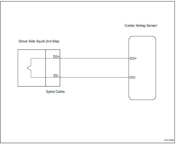
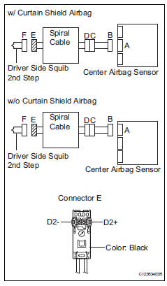
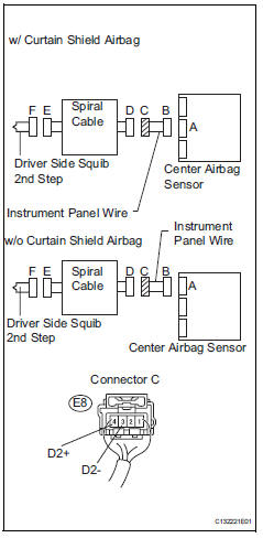
The driver side squib 2nd step circuit consists of the center airbag sensor, the spiral cable and the steering pad.
The circuit instructs the srs to deploy when the deployment conditions are met.
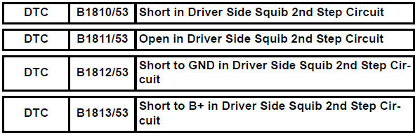
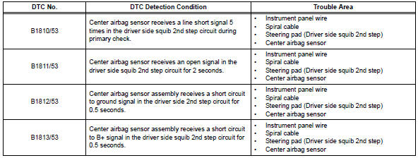
These dtcs are recorded when a malfunction is detected in the driver side squib 2nd step circuit.
Wiring diagram
Inspection procedure
Hint:
- Perform the simulation method by selecting the "check mode" (signal check) with the intelligent tester (see page rs-52).
- After selecting the "check mode" (signal check), perform the simulation method by wiggling each connector of the airbag system or driving the vehicle on a city or rough road (see page rs-52).
- Check steering pad (driver side squib 2nd step)
- Turn the ignition switch off.
- Disconnect the cable from the negative (-) battery terminal, and wait for at least 90 seconds.
- Disconnect the connectors from the steering pad.
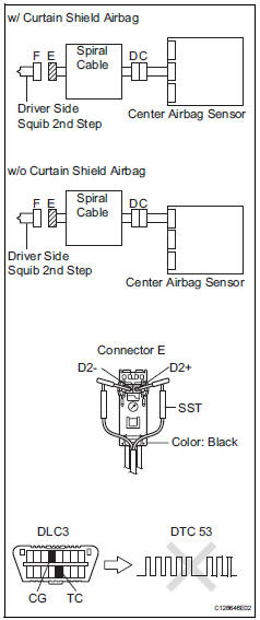
- Connect the white wire side of sst to the spiral cable connector e.
Caution:
Never connect a tester to the steering pad (driver side squib 2nd step) for measurement, as this may lead to a serious injury due to airbag deployment.
Notice:
- Do not forcibly insert sst into the terminals of the connector when connecting.
- Insert sst straight into the terminals of the connector.
Sst 09843-18060
- Connect the cable to the negative (-) battery terminal, and wait for at least 2 seconds.
- Turn the ignition switch on, and wait for at least 60 seconds.
- Clear the dtcs (see page rs-49).
- Turn the ignition switch off.
- Turn the ignition switch on, and wait for at least 60 seconds
- Check the dtcs (see page rs-49).
Ok: dtc b1810, b1811, b1812, b1813 or 53 is not output.
Hint:
Dtcs other than dtc b1810, b1811, b1812, b1813 or 53 may be output at this time, but they are not related to this check.


- Check connector
- Turn the ignition switch off.
- Disconnect the cable from the negative (-) battery terminal, and wait for at least 90 seconds.
- Disconnect sst from the spiral cable.
- Check that the spiral cable connector (on the steering pad side) is not damaged.
Ok: lock button is not disengaged, and claw of lock is not deformed or damaged.


- Check driver side squib 2nd step circuit
- Disconnect the connector from the center airbag sensor.
- Connect the cable to the negative (-) battery terminal, and wait for at least 2 seconds.
- Turn the ignition switch on.
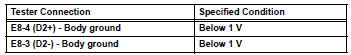
- Measure the voltage of the wire harness side connector.
Standard voltage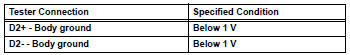
- Turn the ignition switch off.
- Disconnect the cable from the negative (-) battery terminal, and wait for at least 90 seconds.
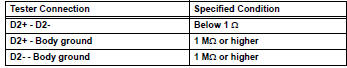
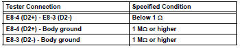
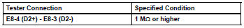
- Measure the resistance of the wire harness side connector.
Standard resistance
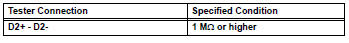
- Release the activation prevention mechanism built into connector b (see page rs-37).
- Measure the resistance of the wire harness side connector.
Standard resistance

- Check instrument panel wire
- Restore the released activation prevention mechanism of connector b to its original position.
- Disconnect the instrument panel wire connector from the spiral cable.
- Connect the cable to the negative (-) battery terminal, and wait for at least 2 seconds.
- Turn the ignition switch on.
- Measure the voltage of the wire harness side connector.
Standard voltage
- Turn the ignition switch off.
- Disconnect the cable from the negative (-) battery terminal, and wait for at least 90 seconds.
- Measure the resistance of the wire harness side connector.
Standard resistance
- Release the activation prevention mechanism built into connector b (see page rs-37).
- Measure the resistance of the wire harness side connector.
Standard resistance

Replace spiral cable
 Short in front passenger side squib circuit
Description
The front passenger side squib circuit consists of the center airbag sensor
and the front passenger airbag.
The circuit instructs the srs to deploy when the deployment conditions ...
 Short in front passenger side squib 2nd step circuit
Description
The front passenger side squib 2nd step circuit consists of the center airbag
sensor and the front
passenger airbag.
The circuit instructs the srs to deploy when the deployment ...
Other materials:
Trailer tongue weight
A recommended tongue weight varies in accordance with the types
of trailers or towing as described below.
To ensure the recommended values shown below, the trailer must
be loaded by referring to the following instructions.
Tongue weight
The gross trailer weight should be distributed so ...
Glossary of sae and toyota terms
This glossary lists all sae-j1930 terms and abbreviations
used in this manual in compliance with sae
recommendations, as well as their toyota equivalents.
...
On-vehicle inspection
Check battery condition
Notice:
If the battery is weak or if the engine is difficult to
start, perform the following procedures.
Check the battery for damage and deformation. If
severe damage, deformation or leakage is found,
replace the battery.
Check the electrolyte quantity of e ...
