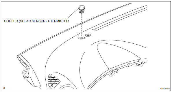
Toyota RAV4 (XA40) 2013-2018 Service Manual: Solar sensor (for automatic air conditioning system)
Components
Removal
- Disconnect cable from negative battery terminal
Caution:
Wait at least 90 seconds after disconnecting the cable from the negative (-) battery terminal to prevent airbag and seat belt pretensioner activation.
- Remove solar sensor
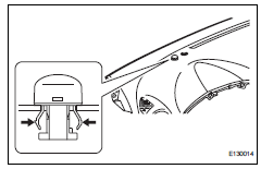
- Using a screwdriver, pull out the solar sensor, then disconnect the connector.
Hint:
Tape the screwdriver tip before use.
Inspection
- Inspect solar sensor
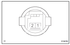
- Using an ohmmeter, connect the positive lead to terminal 2 and the negative lead to terminal 1, then measure the resistance between the terminals.
Standard resistance 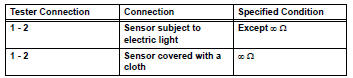
Notice:
The connection procedure for using a digital tester such as a toyota electrical tester is shown above. When using an analog tester, connect the positive (+) lead to terminal 1 and the negative (-) lead to terminal 2 of the a/c solar sensor.
Hint:
- As the inspection light is moved away from the sensor, the voltage increases.
- Use an incandescent lamp for inspection. Bring it within 30 cm (11.8 In.) Of the a/c solar sensor.
If the result is not as specified, replace the solar sensor.
Installation
- Install solar sensor
- Connect the connector, and then push in the solar sensor.
- Connect cable to negative battery terminal
- Check srs warning light
- Check the srs warning light (see page rs-37).
 Evaporator temperatur sensor
Removal
Remove air conditioning unit
Remove the air conditioning radiator (see page ac-
185).
Remove evaporator temperature sensor
(see page ac-193)
Inspection
Inspect evapo ...
 Heater relay
On-vehicle inspection
Inspect relay (marking: htr)
Measure the resistance of the htr relay.
Standard resistance
If the result is not as specified, replace the relay. ...
Other materials:
Fog light switch
The fog lights offer
improved visibility in difficult
driving conditions,
such as in rain and fog.
Operating procedure
*1 or
*2 Turns the
fog lights off
Turns the fog lights on
*1:For the U.S.A.
*2:For Canada
â– Fog lights can be used when
The headlights are on in low beam. ...
Ecm / pcm internal engine off timer performance
Dtc summary
Description
To ensure the accuracy of the evap (evaporative emission) monitor values, the
soak timer, which is built
into the ecm, measures 5 hours (+-15 minutes) from when the ignition switch is
turned off, before the
monitor is run. This allows the fuel to cool down, wh ...
Inside rear view mirror
The rear view mirror’s position can be adjusted to enable sufficient
confirmation of the rear view.
Adjusting the height of rear view mirror
The height of the rear view mirror can be adjusted to suit your driving
posture.
Adjust the height of the rear view
mirror by moving it up and down.
...
