Toyota RAV4 (XA40) 2013-2018 Service Manual: Sruepsptrleaminetnstal restraint system center airbag sensor assembly
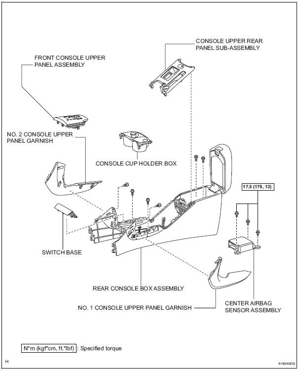
Components
On-vehicle inspection
- Check center airbag sensor assembly (vehicle not involved in collision and airbag not deployed)
- Perform a diagnostic system check (see page rs- 49).
- Check center airbag sensor assembly (vehicle involved in collision and airbag not deployed)
- Perform a diagnostic system check (see page rs- 49).
- Check center airbag sensor assembly (vehicle involved in collision and airbag deployed)
- Replace the center airbag sensor.
Caution:
For removal and installation of the center airbag sensor, be sure to follow the correct procedures.
Removal
Caution:
Be sure to read the precautionary notices concerning the srs airbag system before servicing it (see page rs-1).
- Disconnect cable from negative battery terminal
Caution:
Wait at least 90 seconds after disconnecting the cable from the negative (-) battery terminal to prevent airbag and seat belt pretensioner activation.
- Remove no. 1 Console upper panel garnish (see page ip-17)
- Remove no. 2 Console upper panel garnish (see page ip-18)
- Remove upper console panel sub-assembly (see page ip-18)
- Remove switch base (see page ip-18)
- Remove console cup holder box (see page ip-18)
- Remove upper rear console panel subassembly (see page ip-19)
- Remove console rear end panel (see page ip- 19)
- Remove no. 1 Instrument panel bracket cover inner lh (see page ip-19)
- Remove no. 1 Instrument panel bracket cover inner rh (see page ip-19)
- Remove rear console box assembly (see page ip-20)
- Remove center airbag sensor assembly
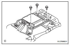
- Disconnect the airbag sensor connectors.
- Remove the 3 bolts and airbag sensor.
Installation
Caution:
Be sure to read the precautionary notices concerning the srs airbag system before servicing it (see page rs-1).
- Install center airbag sensor assembly
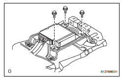
- Install the airbag sensor with the 3 bolts.
Torque: 17.5 N*m (179 kgf*cm, 13 ft.*Lbf)
Notice:
- If the airbag sensor has been dropped, or there are any cracks, dents or other defects in the case, bracket or connector, replace it with a new one.
- When installing the airbag sensor, be careful that the srs wiring does not interfere with other parts and that it is not pinched between other parts.
- Connect the airbag sensor connectors.
- Install rear console box assembly (see page ip-26)
- Install no. 1 Instrument panel bracket cover inner lh (see page ip-26)
- Install no. 1 Instrument panel bracket cover inner rh (see page ip-26)
- Install console rear end panel (see page ip- 26)
- Install upper rear console panel subassembly (see page ip-27)
- Install console cup holder box (see page ip-27)
- Install switch base (see page ip-27)
- Install upper console panel sub-assembly (see page ip-27)
- Install no. 2 Console upper panel garnish (see page ip-28)
- Install no. 1 Console upper panel garnish (see page ip-28)
- Connect cable to negative battery terminal
- Check srs warning light
- Check the srs warning light (see page rs-34).
 Disposal
Hint:
When scrapping a vehicle equipped with srs or disposing of
the front seat side airbag, be sure to deploy the airbag first in
accordance with the procedure described below. If any
abnormality ...
 Front airbag sensor
Components
On-vehicle inspection
Check front airbag sensor (vehicle not
involved in collision and airbag not
deployed)
Perform a diagnostic system check (see page rs-
49).
C ...
Other materials:
Cleaning and protecting the vehicle exterior
Perform the following to
protect the vehicle and
maintain it in prime condition:
Cleaning instructions
Working from top to bottom,
liberally apply water to the
vehicle body, wheel wells and
underside of the vehicle to
remove any dirt and dust.
Wash the vehicle body using
a sponge or soft clo ...
Transmitter id
Description
The tire pressure warning valve and transmitter that is installed in the
tires and wheels measures the air
pressure of the tires. The measured values are transmitted to the tire pressure
warning receiver on the
body as radio waves and then sent to the tire pressure warning ecu ...
Removal
Disconnect cable from negative battery
terminal
Caution:
Wait at least 90 seconds after disconnecting the
cable from the negative (-) battery terminal to
prevent airbag and seat belt pretensioner activation.
Disconnect cable from positive battery
terminal
Remove battery clamp
...
