Toyota RAV4 (XA40) 2013-2018 Service Manual: Stop light switch circuit
![]()
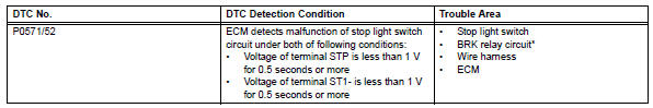
Description
While driving with the cruise control, if the ecm detects that the brake pedal is depressed, the cruise control operation will be canceled. The stop light switch sends brake pedal status signals to the ecm.
When the brake pedal is not depressed, terminal st1- is equal to the positive (+) battery voltage and terminal stp is below 1 v. When the brake pedal is depressed, the ecm cancels cruise control operation.
The ecm outputs this dtc when the voltage of terminals st1- and stp are both below 1 v for 0.5 Seconds or more at the same time. The fail-safe function operates to enable normal driving even if there is a malfunction in the stop light signal circuit.
Hint:
*: W/ vehicle stability control system
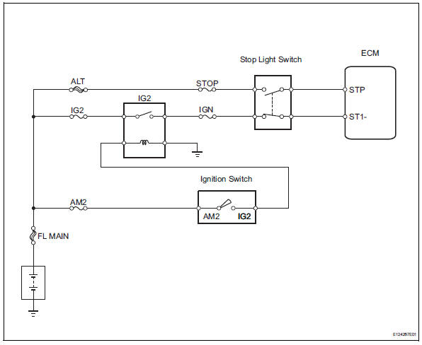
Wiring diagram
Inspection procedure
- Read value of intelligent tester (stop light switch)
- Check the data list for proper functioning of the stop light switch.
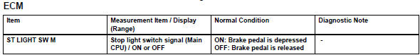
Ok: display changes according to brake pedal operation described in above table.


- Inspect fuse (stop, ign, ig2)
- Remove the stop and ign fuses from the instrument panel junction block.
- Remove the ig2 fuse from the engine room no. 1 Relay block.
- Measure the resistance of the fuses.
Standard resistance:
below 1 


- Inspect ig2 relay
- Remove the ig2 relay from the instrument panel junction block.
- Measure the resistance of the relay.
Standard resistance 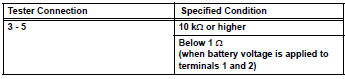


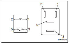
- Inspect stop light switch
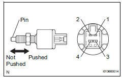
- Remove the stop light switch.
- Measure the resistance of the switch.
Standard resistance 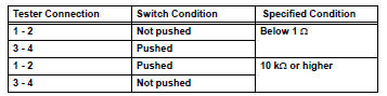


- Check wire harness (switch - battery)
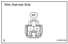
- Disconnect the a3 switch connector.
- Measure the voltage of the wire harness side connector.
Standard voltage 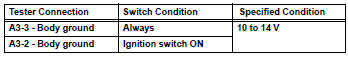

- Check wire harness (ecm - battery)
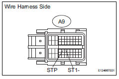
- Disconnect the a9 ecm connector.
- Turn the ignition switch on.
- Measure the voltage of the wire harness side connector.
Standard voltage 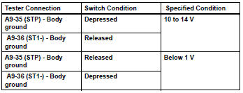

Replace ecm
 Vehicle speed sensor
Description
Refer to the sfi system (see page es-224).
Wiring diagram
Refer to the sfi system (see page es-224).
Inspection procedure
Refer to the sfi system (see page es-224). ...
 Input signal circuit abnormal
Description
This dtc expresses the internal abnormalities of the ecm.
Inspection procedure
Check for dtc
Clear the dtc (see page cc-15).
Check for dtc (see page cc-15).
Ok:
dtc i ...
Other materials:
BSM (Blind Spot Monitor)
The Blind Spot Monitor is a
system that uses rear side
radar sensors installed on
the inner side of the rear
bumper on the left and right
side to assist the driver in
confirming safety when
changing lanes.
WARNING
â– Cautions regarding the use of
the system
The driver is solely responsible
for sa ...
Pig power supply voltage malfunction
Description
When a problem occurs in the system, the power source relay circuit is shut
off to stop the power assist.
Wiring diagram
Inspection procedure
Read value of intelligent tester (pig power supply)
Connect the intelligent tester (with can vim) to the
dlc3.
Turn ...
Wireless remote
control/electronic
key battery
Replace the battery with a new one if it is depleted.
You will need the following items:
Flathead screwdriver
Small flathead screwdriver
Lithium battery cr2016 (vehicles without a smart key system), or
cr2032 (vehicles with a smart key system)
Replacing the battery
Vehicles without a ...
