Toyota RAV4 (XA40) 2013-2018 Service Manual: Diagnostic trouble code chart
Hint:
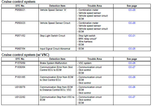
If a trouble code is displayed during the dtc check, check the trouble areas listed for that code in the table below and proceed to the appropriate page.
- Vehicle speed sensor
- Stop light switch circuit
- Input signal circuit abnormal
- Brake system malfunction
- Communication
- Cruise control switch circuit
 Data list / active tes
Read data list
Hint:
Using the intelligent tester's data list allows switch,
sensor, actuator and other item values to be read without
removing any parts. Reading the data list early in
trou ...
 Vehicle speed sensor
Description
Refer to the sfi system (see page es-224).
Wiring diagram
Refer to the sfi system (see page es-224).
Inspection procedure
Refer to the sfi system (see page es-224). ...
Other materials:
Data list / active test
Read data list
Hint:
Using the intelligent tester's data list allows switch,
sensor, actuator and other item values to be read without
removing any parts. Reading the data list early in
troubleshooting is one way to save time.
Connect the intelligent tester (with can vim) to the
dlc3 ...
Downhill assist control system
The downhill assist control
system helps to prevent
excessive speed on steep
downhill slopes.
The system will operate
when the vehicle is traveling
under 15 mph (25 km/h) with
the accelerator and brake
pedals released.
WARNING
â– When using downhill assist
control system
Do not rely overmuch on the ...
Rear upper control arm
Components
Removal
Hint:
Use the same procedures for the rh side and lh side.
The procedures listed below are for the lh side.
Remove rear wheel
Disconnect skid control sensor wire (for
2wd) (see page bc-198)
Disconnect rear speed sensor lh (for 4wd)
(see page bc-205)
Rem ...
