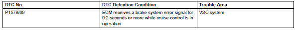
Toyota RAV4 (XA40) 2013-2018 Service Manual: Brake system malfunction
![]()
Description
This dtc is output when the vsc system has a problem. Check the vsc system when this dtc is output.
Inspection procedure
Hint:
This circuit uses can communication. Therefore, if there are any malfunctions in the communication circuit, one or more dtcs in the can communication system are output.
- Check brake system
Refer to how to proceed with troubleshooting (see page bc-20).
 Input signal circuit abnormal
Description
This dtc expresses the internal abnormalities of the ecm.
Inspection procedure
Check for dtc
Clear the dtc (see page cc-15).
Check for dtc (see page cc-15).
Ok:
dtc i ...
 Communication
Description
The skid control ecu sends signals such as cruise control cancel demand
signals and brake operation
demand from ecm response signals to the ecm when the cruise control system is in ...
Other materials:
Side airbag sensor
Components
On-vehicle inspection
Check side airbag sensor (vehicle not
involved in collision)
Perform a diagnostic system check (see page rs-
49).
Check side airbag sensor (vehicle involved
in collision and airbag has not deployed)
Perform a diagnostic system check ( ...
Multi-terrain Select (AWD
vehicles)
Multi-terrain Select is
designed to control AWD,
brake and driving force systems
in accordance with the
road condition. Use the system
when driving over
muddy, sandy or rough road
surfaces.
WARNING
â– Before using Multi-terrain
Select
Make sure to observe the following
precautions. Failure to
observ ...
Catalyst monitor (active air-fuel ratio control type)
Preconditions
The monitor will not run unless:
The mil is off.
Drive pattern
Connect the intelligent tester to the dlc3.
Turn the ignition switch on.
Turn the tester on.
Clear dtcs (if set) (see page es-35).
Start the engine and warm it up.
Drive the vehicle at be ...
