Toyota RAV4 (XA40) 2013-2018 Service Manual: Driver side seat belt warning light does not operate
Description
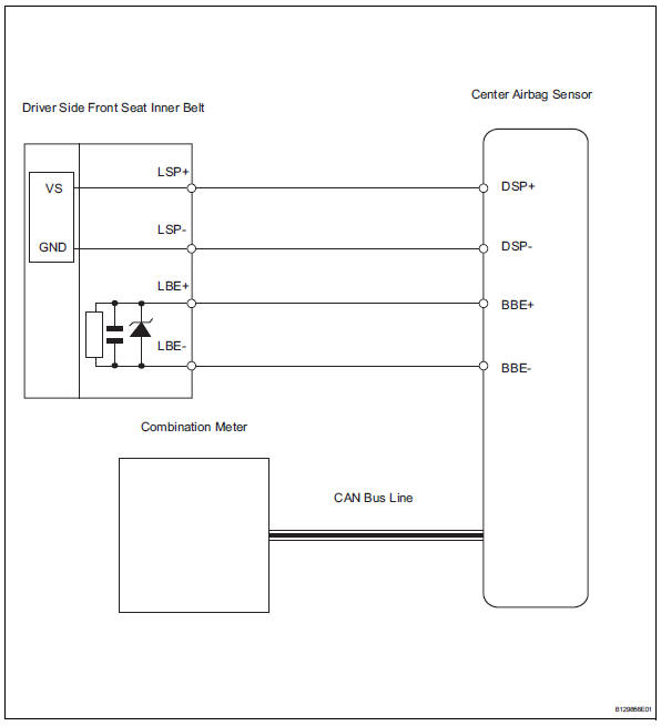
When the ignition switch is on, the center airbag sensor transmits front seat inner belt status signals to the combination meter through the can bus line. If the driver seat belt is not fastened, the combination meter blinks the driver side seat belt warning light. If the seat belt is fastened, the warning light goes off.
Notice:
The seat belt warning system uses the can bus line. Before troubleshooting the seat belt warning system, perform "communication function check" by following "how to proceed with troubleshooting" to confirm that the communication systems are normal.
Wiring diagram
Inspection procedure
- Perform active test using intelligent tester
- Select the active test, use the intelligent tester to generate a control command, and then check that the seat belt warning light operates.
Center airbag sensor:

Ok: driver side seat belt warning light operates normally.

Replace center airbag sensor assembly
 On-vehicle inspection
Check driver side seat belt warning light
Turn the ignition switch on.
When the driver side seat belt is not fastened, check
that the combination meter's driver side seat belt
warning l ...
 Front passenger side seat belt warning light malfunction
Description
When the ignition switch is on, the center airbag sensor transmits front seat
inner belt status signals to
the combination meter through the can bus line. If the front passenger seat b ...
Other materials:
Power steering ecu communication stop mode
Description
Wiring diagram
Inspection procedure
Notice:
Turn the ignition switch off before measuring the resistances of the
main wire and the branch
wire.
After the ignition switch is turned off, check that the key reminder
warning system and light
reminder warning system ...
Tire pressure warning light circuit
Description
If the tire pressure warning ecu detects trouble, the tire pressure warning
light turns on and tire pressure
monitor is canceled at the same time. At this time, the ecu records a dtc in
memory.
Connect terminals tc and cg of the dlc3 to make the tire pressure warning light
bli ...
Power supply relay failure
Description
If the power steering ecu detects these dtcs, it shuts off the motor relay
circuit (built into the power
steering ecu) and stops power assist.
Inspection procedure
Reconfirm dtc
Check for dtc.
Ok:
dtc is not output.
Replace power steering ecu ...
