Toyota RAV4 (XA40) 2013-2018 Service Manual: Front passenger side rear airbag sensor circuit malfunction
Description
The rear airbag sensor rh consists of parts including the diagnostic circuit and the lateral deceleration sensor.
When the center airbag sensor receives signals from the lateral deceleration sensor, it determines whether or not the srs should be activated.
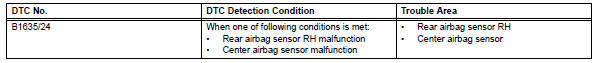
Dtc b1635/24 is recorded when a malfunction is detected in the rear airbag sensor rh circuit.
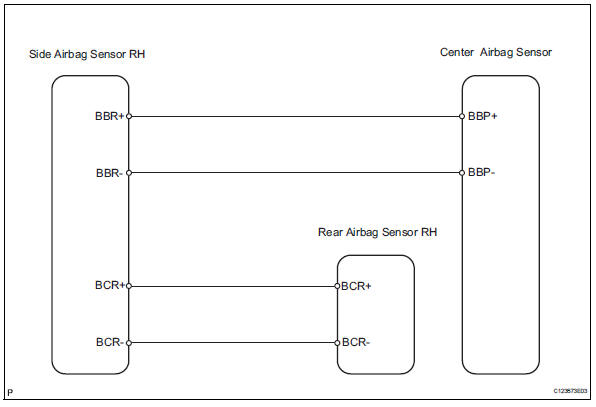
Wiring diagram
inspection procedure
- Check rear airbag sensor rh
- Turn the ignition switch off.
- Disconnect the cable from the negative (-) battery terminal, and wait for at least 90 seconds.
- Interchange the side airbag sensor rh with the side airbag sensor lh and connect the connectors to them.
- Connect the cable to the negative (-) battery terminal, and wait for at least 2 seconds
- Turn the ignition switch on, and wait for at least 60 seconds.
- Clear the dtcs (see page rs-49).
- Turn the ignition switch off.
- Turn the ignition switch on, and wait for at least 60 seconds.
- Check the dtcs (see page rs-49).
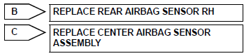
Result 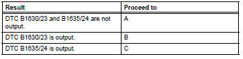
Dtcs other than dtc b1630/23 and b1635/24 may be output at this time, but they are not related to this check.

Use simulation method to check
 Driver side rear airbag sensor circuit malfunction
Description
The rear airbag sensor lh consists of parts including the diagnostic circuit
and the lateral deceleration
sensor.
When the center airbag sensor receives signals from the lateral ...
 Driver side satellite sensor bus initialization incomplete
Description
The side airbag sensor lh consists of part including the diagnostic circuit
and the lateral deceleration
sensor.
When the center airbag sensor receives signals from the lateral ...
Other materials:
Child restraint seat tether anchor
Components
Removal
Remove child restraint seat tether anchor cover
Using a screwdriver, detach the 4 claws and remove
the cover.
Hint:
Tape the screwdriver tip before use.
Remove roof headlining assembly
Hint:
It is not necessa ...
All-wheel drive lock
switch (awd models)
All-wheel drive lock mode can be used when a large amount of
drive power needs to be applied to all the wheels, such as when
the vehicle gets stuck in mud and you need to free it.
Press the switch.
The torque of the engine is distributed
to the rear wheels to the maximum
extent possible in
ac ...
Removal (2006/01- )
Disconnect cable from negative battery
terminal
Caution:
Wait at least 90 seconds after disconnecting the
cable from the negative (-) battery terminal to
prevent airbag and seat belt pretensioner activation.
Remove air cleaner case sub-assembly (for
2az-fe)
Remove the air clea ...
