
Toyota RAV4 (XA40) 2013-2018 Service Manual: Driver side rear airbag sensor circuit malfunction

Description
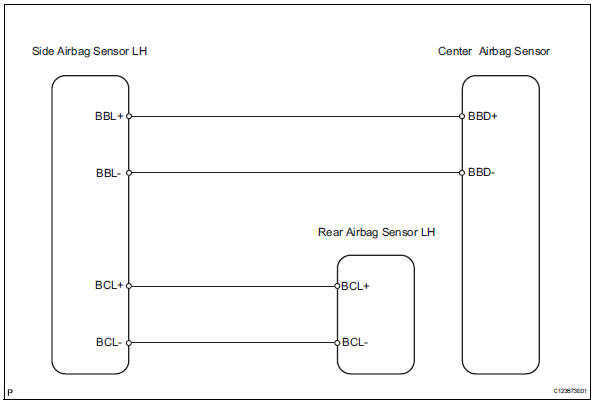
The rear airbag sensor lh consists of parts including the diagnostic circuit and the lateral deceleration sensor.
When the center airbag sensor receives signals from the lateral deceleration sensor, it determines whether or not the srs should be activated.
Dtc b1630/23 is recorded when a malfunction is detected in the rear airbag sensor lh circuit.

Wiring diagram
Inspection procedure
- Check rear airbag sensor lh
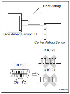
- Turn the ignition switch off.
- Disconnect the cable from the negative (-) battery terminal, and wait for at least 90 seconds.
- Interchange the side airbag sensor rh with the side airbag sensor lh and connect the connectors to them.
- Connect the cable to the negative (-) battery terminal, and wait for at least 2 seconds.
- Turn the ignition switch on, and wait for at least 60 seconds.
- Clear the dtcs (see page rs-49).
- Turn the ignition switch off.
- Turn the ignition switch on, and wait for at least 60 seconds.
- Check the dtcs (see page rs-49).
Result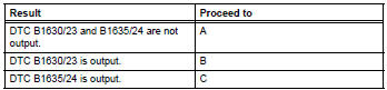
Hint:
Dtcs other than dtc b1630/23 and b1635/24 may be output at this time, but they are not related to this check.

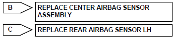
Use simulation method to check
 Front passenger side - side airbag sensor assembly initialization incomplete
Description
The side airbag sensor rh consists of parts including the diagnostic circuit
and the lateral deceleration
sensor.
When the center airbag sensor receives signals from the lateral ...
 Front passenger side rear airbag sensor circuit malfunction
Description
The rear airbag sensor rh consists of parts including the diagnostic circuit
and the lateral deceleration
sensor.
When the center airbag sensor receives signals from the lateral ...
Other materials:
Exhaust pipe
Installation
Install front exhaust pipe assembly
Using a vernier caliper, measure the free length of
the compression spring.
Minimum length:
41.5 Mm (1.634 In.)
If the length is less than the minimum, replace the
compression spring.
Install a new gasket by hand so that its ...
Problem symptoms table
Hint:
Use the table below to help determine the cause of the
problem symptom. The potential causes of the symptoms
are listed in order of probability in the "suspected area"
column of the table. Check each symptom by checking the
suspected areas in the order they are listed. Re ...
Emission inspection and maintenance (I/M) programs
Some states have vehicle
emission inspection programs
which include OBD
(On Board Diagnostics)
checks. The OBD system
monitors the operation of
the emission control system.
If the malfunction indicator
lamp comes on
The OBD system determines
that a problem exists somewhere
in the emission control
sy ...
