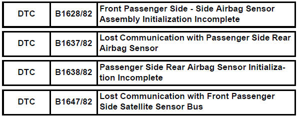
Toyota RAV4 (XA40) 2013-2018 Service Manual: Front passenger side - side airbag sensor assembly initialization incomplete
Description
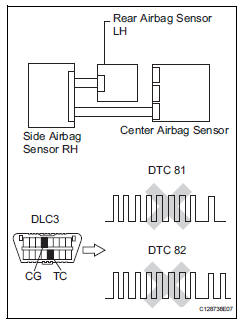
The side airbag sensor rh consists of parts including the diagnostic circuit and the lateral deceleration sensor.
When the center airbag sensor receives signals from the lateral deceleration sensor, it determines whether or not the srs should be activated.
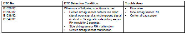
Dtc b1628/82, b1637/82, b1638/82 or b1647/82 is set when a malfunction is detected in the side airbag sensor rh circuit.
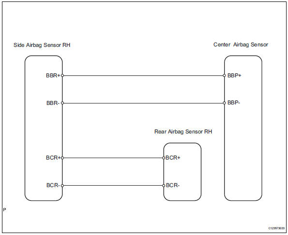
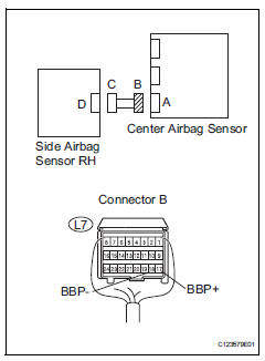
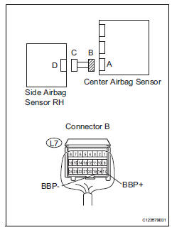
Wiring diagram
Inspection procedure
- Check connection of connector
- Turn the ignition switch off.
- Disconnect the cable from the negative (-) battery terminal, and wait for at least 90 seconds.
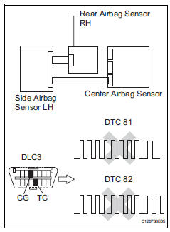
- Check that the connectors are properly connected to the center airbag sensor, rear airbag sensor rh and the side airbag sensor rh.
Ok: the connectors are properly connected.


- Check floor wire (open)
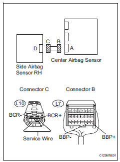
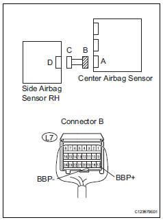
- Disconnect the connectors from the center airbag sensor and the side airbag sensor rh.
- Using a service wire, connect l10-4 (bbr+) and l10-3 (bbr-) of connector c.
Notice:
Do not forcibly insert the service wire into the terminals of the connector when connecting.
- Measure the resistance of the wire harness side connector.
Standard resistance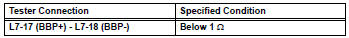

- Check floor wire (short)
- Disconnect the service wire from connector c.
- Measure the resistance of the wire harness side connector.
Standard resistance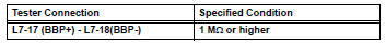

- Check floor wire (to b+)
- Connect the cable to the negative (-) battery terminal, and wait for at least 2 seconds.
- Turn the ignition switch on.
- Measure the voltage of the wire harness side connector.
Standard voltage 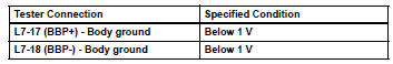


- Check floor wire (to ground)
- Turn the ignition switch off.
- Disconnect the cable from the negative (-) battery terminal, and wait for at least 90 seconds.
- Measure the resistance of the wire harness side connector.
Standard resistance 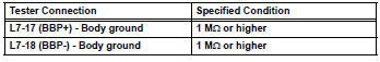


- Check floor wire (open)
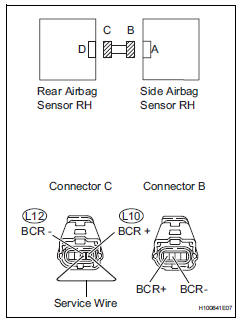
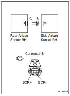
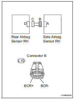
- Disconnect the connectors from the side airbag sensor rh and the rear airbag sensor rh.
- Using a service wire, connect l12-1 (bcr-) and l12-2 (bcr+) of connector c.
Notice:
Do not forcibly insert the service wire into the terminals of the connector when connecting.
- Measure the resistance of the wire harness side connector.
Standard resistance 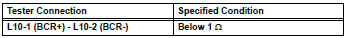

- Check floor wire (short)
- Disconnect the service wire from connector c.
- Measure the resistance of the wire harness side connectors.
Standard resistance 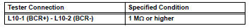

- Check floor wire (to b+)
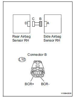
- Connect the cable to the negative (-) battery terminal, and wait for at least 2 seconds.
- Turn the ignition switch on.
- Measure the voltage of the wire harness side connector.
Standard voltage 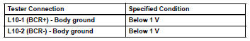

- Check floor wire (to ground)
- Turn the ignition switch off.
- Disconnect the cable from the negative (-) battery terminal, and wait for at least 90 seconds.
- Measure the resistance of the wire harness side connector.
Standard resistance 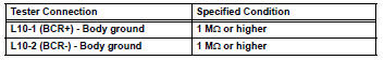

- Check side airbag sensor rh
- Connect the connectors to the center airbag sensor .
- Interchange the side airbag sensor lh with the side airbag sensor rh and connect the connectors to them.
- Connect the cable to the negative (-) battery terminal, and wait for at least 2 seconds
- Turn the ignition switch on, and wait for at least 60 seconds.
- Clear the dtcs (see page rs-49).
- Turn the ignition switch off.
- Turn the ignition switch on, and wait for at least 60 seconds.
- Check for dtcs (see page rs-49).
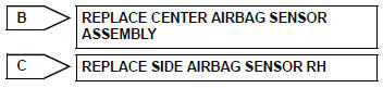
Result 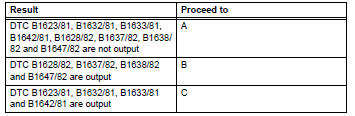
Hint:
Dtcs other than dtc b1623/81, b1632/81, b1633/81, b1642/81, b1628/82, b1637/82, b1638/82 and b1647/ 82 may be output at this time, but they are not related to this check.

- Check rear airbag sensor rh
- Turn the ignition switch off.
- Disconnect the cable from the negative (-) battery terminal, and wait for at least 90 seconds.
- Interchange the rear airbag sensor rh with the rear airbag sensor lh and connect the connectors to them.
- Connect the cable to the negative (-) battery terminal, and wait for at least 2 seconds
- Turn the ignition switch on, and wait for at least 60 seconds.
- Clear the dtcs (see page rs-49).
- Turn the ignition switch on, and wait for at least 60 seconds.
- Check the dtcs (see page rs-49).
Result 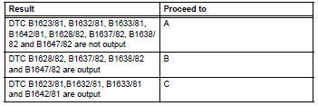

Use simulation method to check
 Lost communication with front passenger side - side airbag sensor assembly
Description
The side airbag sensor rh consists of parts including the diagnostic circuit
and the lateral deceleration
sensor.
When the center airbag sensor receives signals from the lateral ...
 Driver side rear airbag sensor circuit malfunction
Description
The rear airbag sensor lh consists of parts including the diagnostic circuit
and the lateral deceleration
sensor.
When the center airbag sensor receives signals from the lateral ...
Other materials:
Battery current sensor
On-vehicle inspection
Check battery current sensor assembly
Measure the resistance of the sensor.
Standard resistance
If the result is not as specified, replace the sensor
assembly.
Measure the resistance of the sensor.
Standard resistance
If the result is not as specified, ...
Rear occupant classification sensor rh collision detection
Description
Dtc b1788 is output when the occupant classification ecu receives a collision
detection signal sent by
the rear occupant classification sensor rh when an accident occurs.
Dtc b1788 is also output when the front seat rh is subjected to a strong impact,
even if an actual
acci ...
Fuel system
Precaution
Before working on fuel system
Do not work near an open flame.
Keep gasoline away from rubber and leather parts.
Discharge the fuel pressure before disconnecting
the fuel line to prevent gasoline from spilling out.
Refer to the following procedure.
Discharge fuel ...
