Toyota RAV4 (XA40) 2013-2018 Service Manual: Lost communication with front passenger side - side airbag sensor assembly

Description
The side airbag sensor rh consists of parts including the diagnostic circuit and the lateral deceleration sensor.
When the center airbag sensor receives signals from the lateral deceleration sensor, it determines whether or not the srs should be activated.
Dtc b1627/82 is set when a malfunction is detected in the side airbag sensor rh circuit.
Wiring diagram
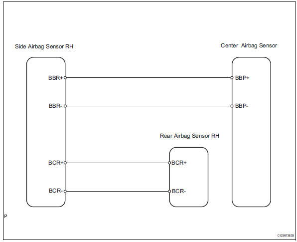
Inspection procedure
- Check connection of connector
- Turn the ignition switch off.
- Disconnect the cable from the negative (-) battery terminal, and wait for at least 90 seconds.
- Check that the connectors are properly connected to the center airbag sensor, rear airbag sensor rh and the side airbag sensor rh.
Ok: the connectors are properly connected.


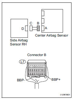
- Check floor wire (open)
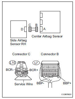
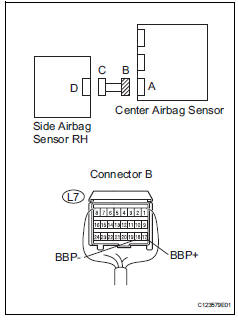
- Disconnect the connectors from the center airbag sensor and the side airbag sensor rh.
- Using a service wire, connect l10-4 (bbr+) and l10-3 (bbr-) of connector c.
Notice:
Do not forcibly insert the service wire into the terminals of the connector when connecting.
- Measure the resistance of the wire harness side connectors.
Standard resistance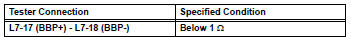

- Check floor wire (short)
- Disconnect the service wire from connector c.
- Measure the resistance of the wire harness side connector.
Standard resistance 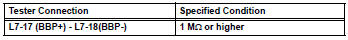


- Check floor wire (to b+)
- Connect the cable to the negative (-) battery terminal, and wait for at least 2 seconds.
- Turn the ignition switch on.
- Measure the voltage of the wire harness side connector.
Standard voltage 


- Check floor wire (to ground)
- Turn the ignition switch off.
- Disconnect the cable from the negative (-) battery terminal, and wait for at least 90 seconds.
- Measure the resistance of the wire harness side connector.
Standard resistance 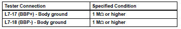

- Check side airbag sensor rh
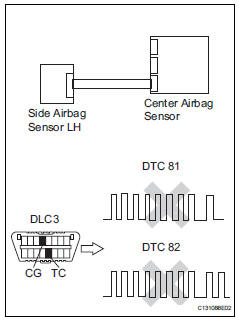
- Connect the connectors to the center airbag sensor.
- Interchange the side airbag sensor rh with the side airbag sensor lh and connect the connectors to them.
- Connect the cable to the negative (-) battery terminal, and wait for at least 2 seconds.
- Turn the ignition switch on, and wait for at least 60 seconds.
- Clear the dtcs (see page rs-49).
- Turn the ignition switch off.
- Turn the ignition switch on, and wait for at least 60 seconds.
- Check for dtcs (see page rs-49).
Result 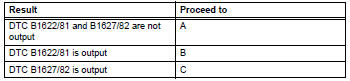
Hint:
Dtcs other than dtc b1622/81 and b1627/82 may be output at this time, but they are not related to this check.


Use simulation method to check
 Front passenger side - side airbag sensor circuit malfunction
Description
The side airbag sensor rh consists of parts including the diagnostic circuit
and the lateral deceleration
sensor.
When the center airbag sensor receives signals from the lateral ...
 Front passenger side - side airbag sensor assembly initialization incomplete
Description
The side airbag sensor rh consists of parts including the diagnostic circuit
and the lateral deceleration
sensor.
When the center airbag sensor receives signals from the lateral ...
Other materials:
Road test
Problem symptom confirmation
Based on the result of the customer problem
analysis, try to reproduce the symptoms. If the
problem is that the transaxle does not shift up, shift
down, or the shift point is too high or too low,
conduct the following road test referring to the
automat ...
Opening/closing the back
door (vehicles with power
back door)
â– Using the wireless remote
control
Press and hold the switch.
The power back door automatically
opens/closes.
Pressing the switch while the power
back door is opening/closing stops
the operation. When the switch is
pressed and held again during the
halted operation, the back door will
perform t ...
Daytime running light relay
On-vehicle inspection
Inspect day time running light relay
Remove the no. 2 Relay, no. 3 Relay and no. 4 Relay
from the engine room no. 2 Relay block.
Measure the resistance of the relays.
Standard resistance:
No. 2, No. 4
No. 3
If the result is not as specified, replace th ...
