Toyota RAV4 (XA40) 2013-2018 Service Manual: System diagram
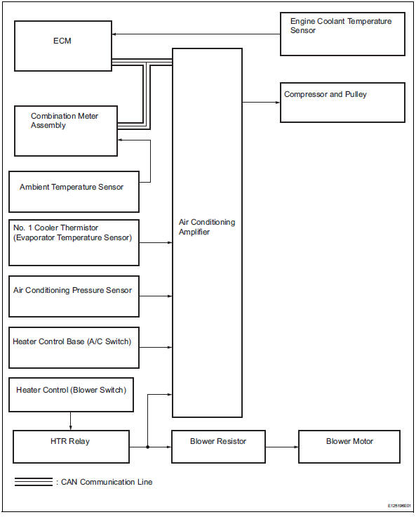
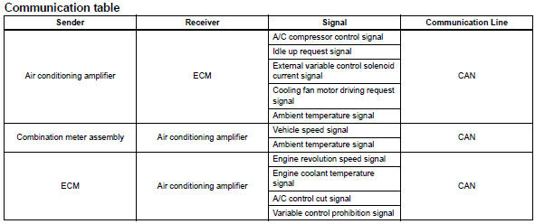
System diagram (2005/11-2006/01)
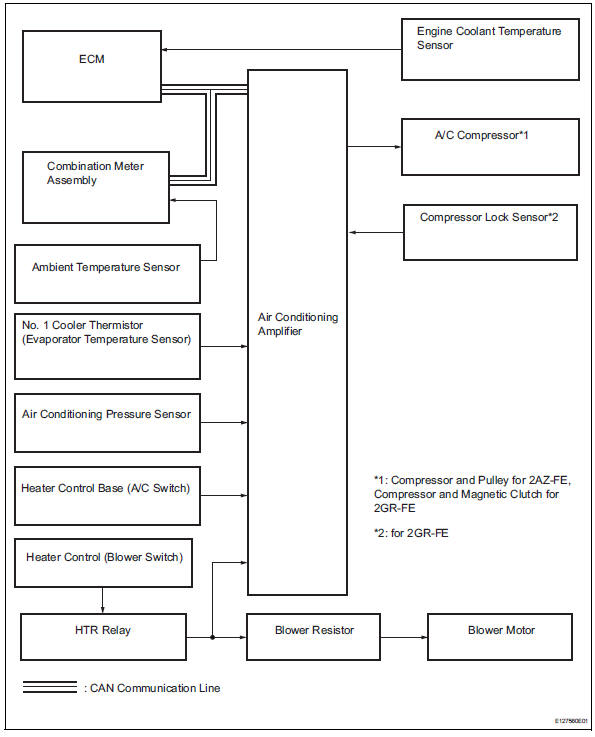
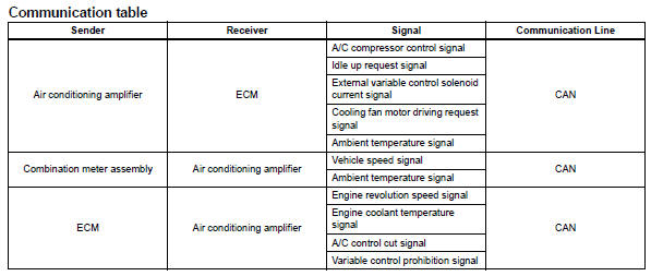
System diagram (2006/01- )

 System description
General
The air conditioning system has the following
features:
The air conditioning amplifier controls the
operation of parts, such as the a/c compressor,
automatically in accord ...
Other materials:
Sensor (motor) failure
Description
When the sliding roof drive gear (sliding roof ecu) detects the motor's
malfunction, and the sliding roof
operation is stopped, dtc b2341 is output. When the sliding roof drive gear
(sliding roof ecu) detects the
gear's malfunction, and the sliding roof operation is stopped, d ...
Valve clearance
Adjustment
Disconnect cable from negative battery
terminal
Caution:
Wait at least 90 seconds after disconnecting the
cable from the negative (-) battery terminal to
prevent airbag and seat belt pretensioner activation.
Remove front wheel rh
Remove no. 1 Engine under cover
Remove ...
Main body ecu communication stop mode
Description
Wiring diagram
Inspection procedure
Notice:
Turn the ignition switch off before measuring the resistances of the
main wire and the branch
wire.
After the ignition switch is turned off, check that the key reminder
warning system and light
reminder warning syste ...
