Toyota RAV4 (XA40) 2013-2018 Service Manual: Tc and cg terminal circuit
Description
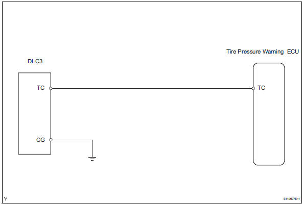
Dtc output mode is set by connecting terminals 13 (tc) and 4 (cg) of the dlc3. The dtcs are indicated by the blinking of the tire pressure warning light.
Wiring diagram
Hint:
When each warning light continues blinking, a ground short in the wiring of terminal tc of the dlc3 or an internal ground short in each ecu may have occurred.
Inspection procedure
Notice:
It is necessary to register an id code after replacing the tire pressure monitor valve and/or the tire pressure warning ecu (see page tw-9).
- Check wire harness (dlc3 - ecu)
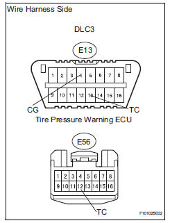
- Disconnect the e13 dlc3 connector.
- Disconnect the e56 ecu connector.
- Measure the resistance of the wire harness side connectors.
Standard resistance 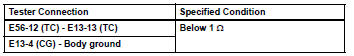

Proceed to next circuit inspection shown in problem symptoms table

 Removal
Disconnect cable from negative battery
terminal
Caution:
Wait at least 90 seconds after disconnecting the
cable from the negative (-) battery terminal to
prevent airbag and seat belt preten ...
Other materials:
Do-it-yourself service precautions
If you perform maintenance
by yourself, be sure to follow
the correct procedure
as given in these sections.
Maintenance
WARNING
The engine compartment contains
many mechanisms and fluids that
may move suddenly, become hot,
or become electrically energized.
To avoid death or serious injury,
obser ...
If your vehicle overheats
The following may indicate that your vehicle is overheating.
The high engine coolant temperature warning light Comes
on or a loss of engine power is experienced. (For example, the
vehicle speed does not increase.)
Steam comes out from under the hood.
Correction procedures
Stop ...
Wireless remote control
The keys are equipped with the
following wireless remote control:
Vehicles without smart key
system
Locks all the doors
Sounds the alarm
Unlocks all the doors
Opens the side windows*
*: This setting must be customized
at your Toyota dealer.
Vehicles with smart key system
Locks all the do ...
