Toyota RAV4 (XA40) 2013-2018 Service Manual: Removal
- Discharge refrigerant from refrigeration system (see page ac-172)
- Disconnect cable from negative battery terminal
Caution:
Wait at least 90 seconds after disconnecting the cable from the negative (-) battery terminal to prevent airbag and seat belt pretensioner activation.
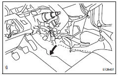
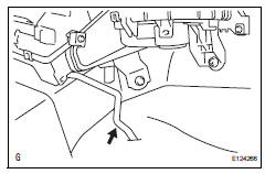
- Remove tube sub-assembly
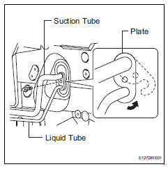
- Remove the bolt.
- Remove plate, as shown in the illustration.
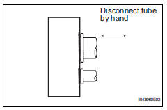
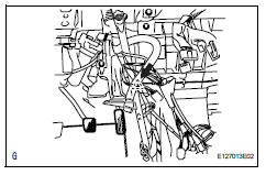
- Disconnect the suction tube and liquid tube.
Notice:
- Do not use a screwdriver or similar tool to disconnect the tube.
- Seal the opening of the disconnected parts using vinyl tape to prevent moisture and foreign matter from entering them.
- Remove the 2 o-rings from the suction tube and liquid tube.
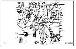
- Disconnect inlet heater water hose
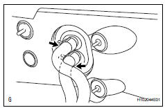
- Using pliers, grip the claws of the clip and slide the clip.
- Disconnect the heater water inlet hose.
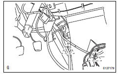
- Disconnect outlet heater water hose
Hint:
Disconnection of the heater water outlet hose is the same as for the heater water inlet hose.
- Remove steering column assembly
- Remove the steering column (see page sr-11).
- Remove upper instrument panel
- Remove the upper instrument panel (see page ip- 4).
- Remove lower instrument panel
- Remove the lower instrument panel (see page ip- 16).
- Remove defroster nozzle assembly
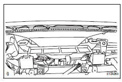
- Detach the 3 claws and remove the defroster nozzle assembly.
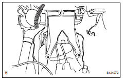
- Remove no. 1 Instrument panel brace subassembly
- Fold the floor carpet back.
- Disconnect the clamp and disconnect the wire harness.
- Remove the bolt, nut, screw, and instrument panel brace.
- Remove air duct rear
- Disconnect the 2 clamps and disconnect the wire harness.
- Detach the 3 claws and remove the air duct rear.
- Remove air duct
- Detach the 2 claws and remove the air duct.
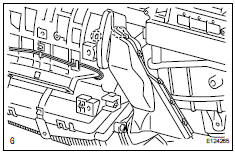
- Remove air conditioning amplifier assembly
- Detach the 2 clamps.
- Disconnect the connector.
- Remove the screw and amplifier.
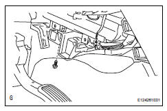
- Remove drain cooler hose
- Remove the drain hose.
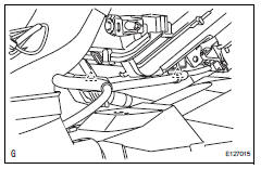
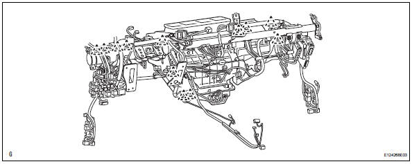
- Remove instrument panel reinforcement
- Disconnect the 12 clamps.
- Remove the 4 bolts and disconnect the ground wire.
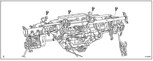
- Remove the 3 bolts.
- Remove the 6 bolts and instrument panel reinforcement.
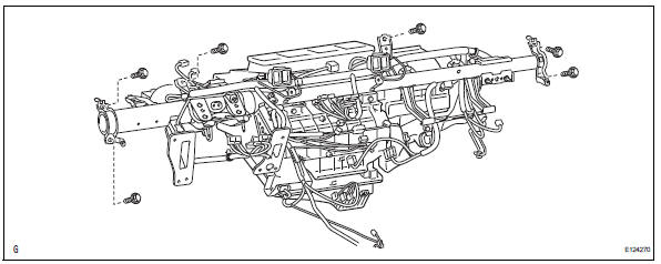
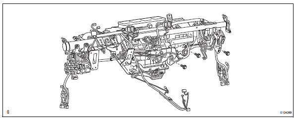
- Remove air conditioner unit assembly
- Remove the bolt, nut and a/c unit.
 Components
...
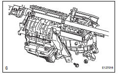
 Disassembly
Remove no. 3 Heater to register duct
Detach the 6 claws and remove the heater to
register duct.
Remove air duct
Detach the 2 claws and remove the air duct.
Remove ...
Other materials:
Only passenger door lock / unlock functions do not operate
Description
The main body ecu receives lock / unlock switch signals and activates the
door lock motor accordingly.
Wiring diagram
Inspection procedure
Read value of intelligent tester (lock position switch)
Use the data list to check if the door lock is
functioning properly.
...
Battery temperature sensor circuit
Description
The battery temperature sensor installed on the battery current sensor
detects battery temperature.
A thermistor is integrated into the battery temperature sensor, and the
resistance in the battery
temperature sensor changes according to the battery temperature.
The r ...
Diagnosis system
Description
The center airbag sensor controls the functions of the
supplemental restraint system (srs) on the vehicle.
Data of the srs can be read in the data link connector
3 (dlc3) of the vehicle. When the system seems to be
malfunctioning, use the intelligent tester to check for a
ma ...
