
Toyota RAV4 (XA40) 2013-2018 Service Manual: Inspection
- Inspect oil pump assembly
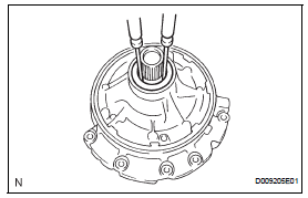
- Turn the drive gear with 2 screwdrivers and make sure it rotates smoothly.
Notice:
Be careful not to damage the oil seal lip.
- Inspect clearance of oil pump assembly
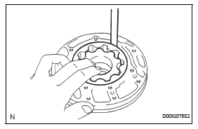
- Push the driven gear to one side of the body. Using a feeler gauge, measure the clearance.
Standard body clearance: 0.10 To 0.17 Mm (0.0039 To 0.0067 In.)
Maximum body clearance: 0.17 Mm (0.0067 In.)
If the body clearance is greater than the maximum, replace the oil pump body sub-assembly.
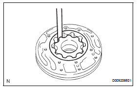
- Measure the tip clearance between the driven gear teeth and drive gear teeth.
Standard tip clearance: 0.07 To 0.15 Mm (0.0028 To 0.0059 In.)
Maximum tip clearance: 0.15 Mm (0.0059 In.)
If the tip clearance is grater than the maximum, replace the oil pump body sub-assembly.
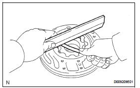
- Using a straightedge and feeler gauge, measure the side clearance of both gears.
Standard side clearance: 0.02 To 0.05 Mm (0.0008 To 0.0020 In.)
Maximum side clearance: 0.05 Mm (0.0020 In.)
Standard drive gear thickness 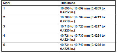
Standard driven gear thickness 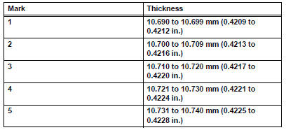
- Inspect front oil pump and gear body subassembly
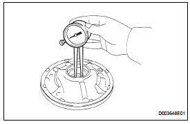
- Using a caliper gauge, measure the inside diameter of the oil pump body bush.
Standard inside diameter: 38.113 To 38.138 Mm (1.50051 To 1.50149 In.)
Maximum inside diameter: 38.188 Mm (1.50346 In.)
If the inside diameter is grater than maximum, replace the oil pump body sub-assembly.
- Inspect stator shaft assembly
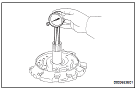
- Using a caliper gauge, measure the inside diameter of the stator shaft bush.
Standard inside diameter: 21.500 To 21.526 Mm (0.84646 To 0.84748 In.)
Maximum inside diameter: 21.57 Mm (0.8492 In.)
If the indicator diameter is greater than the maximum, replace the stator shaft.
 Disassembly
Inspect oil pump assembly (see page ax-218)
Remove clutch drum oil seal ring
Remove the 2 clutch drum oil seal rings.
Remove stator shaft assembly
Using a t30 ''torx'' socke ...
 Reassembly
Install front oil pump oil seal
Using sst and a hammer, install a new oil seal to
the pump.
Sst 09350-32014 (09351-32140)
Hint:
The seal end should be flat with the outer edge of
...
Other materials:
Differential case
Components
Disassembly
Remove front differential ring gear
Place the matchmarks on the ring gear and
differential case.
Remove the 14 bolts.
Using a plastic-faced hammer, tap on the ring gear
to remove it from the case.
Remove front differential case ...
Rear wiper motor
Components
Removal
Disconnect cable from negative battery
terminal
Caution:
Wait at least 90 seconds after disconnecting the
cable from the negative (-) battery terminal to
prevent airbag and seat belt pretensioner activation.
Remove back door center garnish (see page
ed-59)
...
On-vehicle inspection
Check fan and generator v belt
Visually check the drive belt for excessive wear,
frayed cords, etc.
If any defect has been found, replace the drive belt.
Hint:
Cracks on the rib side of a drive belt are considered
acceptable.
If the drive belt has chunks missing from the r ...
