
Toyota RAV4 (XA40) 2013-2018 Service Manual: Reassembly
- Install front oil pump oil seal
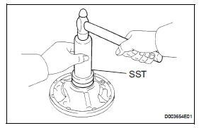
- Using sst and a hammer, install a new oil seal to the pump.
Sst 09350-32014 (09351-32140)
Hint:
The seal end should be flat with the outer edge of the oil pump.
- Coat the lip of the oil seal with petroleum jelly.
- Install front oil pump body o-ring
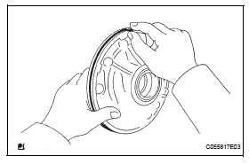
- Coat the new o-ring with atf, and install it to the oil pump body.
- Install front oil pump driven gear
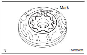
- Coat the front oil pump driven gear with atf, and install it to the oil pump body with the marked side facing up.
- Install front oil pump drive gear
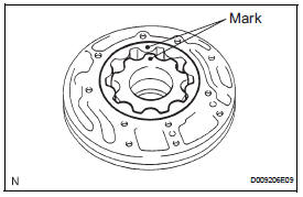
- Coat the front oil pump drive gear with atf, and install it to the oil pump body with the marked side facing up.
- Install stator shaft assembly
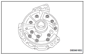
- Set the stator shaft by aligning each bolt hole.
- Using a t30 ''trox'' socket, install the 11 bolts.
Torque: 9.8 N*m (100 kgf*cm, 87 in.*Lbf)
- Install clutch drum oil seal ring
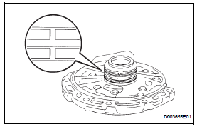
- Install the 2 clutch drum oil seal rings.
Notice:
Do not expand the ring ends excessively.
- Inspect oil pump assembly (see page ax-218)
 Inspection
Inspect oil pump assembly
Turn the drive gear with 2 screwdrivers and make
sure it rotates smoothly.
Notice:
Be careful not to damage the oil seal lip.
Inspect clearance of oil ...
 Second brake piston
Components
Disassembly
Remove 2nd brake piston return spring sub-assembly
Place sst on the return spring and compress.
Using a screwdriver, pry out the snap ring.
Remove the pis ...
Other materials:
Compressor circuit
Description
When the a/c switch is turned on, the magnetic clutch on signal is sent from
the air conditioning
amplifier. Then the mg clt relay turns on to operate the magnetic clutch.
Wiring diagram
Inspection procedure
Perform active test by intelligent tester (a/c mag clutch)
C ...
Removal
Disconnect cable from negative battery
terminal
Caution:
Wait at least 90 seconds after disconnecting the
cable from the negative (-) battery terminal to
prevent airbag and seat belt pretensioner activation.
Remove radiator support opening cover
Remove front wheel rh
Remove no. 1 ...
Installation
Hint:
Use the same procedures for the rh side and lh side.
The procedures listed below are for the lh side.
Install rear door belt moulding assembly
lh
Attach the claws to install the moulding.
Hint:
Confirm that the moulding is firmly installed.
Install rear door tr ...
