Toyota RAV4 (XA40) 2013-2018 Service Manual: Tire pressure warning valve and transmitter
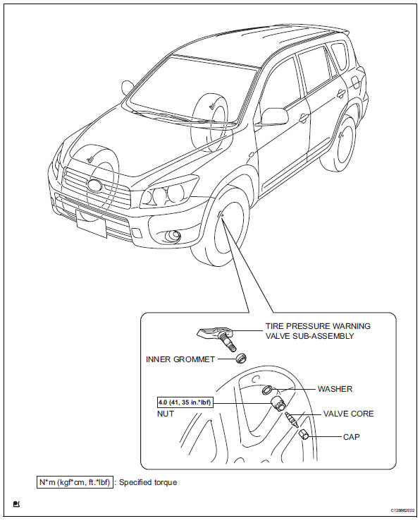
Components
Removal
- Remove front tire
- Remove rear tire
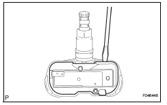
- Remove tire pressure warning valve subassembly
- Remove the valve core and cap, and release air from the tire.
- After ensuring that air is sufficiently released, remove the nut and washer that are used to fix the tire pressure warning valve and drop the valve sensor inside the tire.
Hint:
Keep the removed cap, valve core, nut and washer.
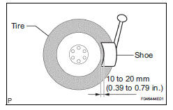
- After dropping the tire pressure warning valve into the tire, disengage the tire bead using the shoe of the tire remover.
Notice:
Be careful not to damage the tire pressure warning valve because of interference between the sensor and tire bead.
- Remove the bead on the upper side.
- Take out the sensor from the tire and remove the bead on the lower side.
- Remove the inner grommet from the tire pressure warning valve.
Hint:
Check that there are no cracks or damage on the grommet. If necessary, replace the grommet, the washer and the nut.
Installation
- Install tire pressure warning valve subassembly
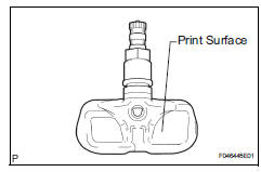
- Insert the tire pressure warning valve into the valve installation hole. Insert it from the inside of the rim so that the print surface can be seen.
Notice:
- Check that there is no visible deformation, damage or other abnormalities on the transmitter.
- Check that there is no foreign matter on the inner grommet and around the rim hole.
- If the tire pressure warning valve is installed in the reverse direction, it may be damaged or fail to transmit signals when the vehicle is driven at high speeds.
- Install the washer on the tire pressure warning valve from the rim side and tighten it with the nut.
Torque: 4.0 N*m (41 kgf*cm, 35 in.*Lbf)
Notice:
- Make sure that there is no foreign matter on the washer and nut.
- If the tire and tire pressure warning valve have been removed, check that there is no damage or cuts visible, and no foreign matter, such as mud, dirt or sand attached to the grommet. Replace the grommet with a new one if any of the defects mentioned above are found.
- Make sure that there is no oil, water or lubricant around the rim hole, tire pressure warning valve, washer and nut. Failing to do so may result in improper installation.
- After the tire is inflated, the valve nut may be loose.
Retighten the nut to the specified torque and then check for air leaks with soapy water.
Torque: 4.0 N*m (41 kgf*cm, 35 in.*Lbf)
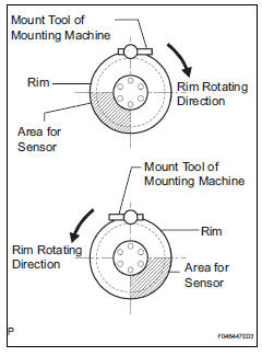
- Set the wheel disc to the mounting machine and install the lower tire bead. Position the main body of the valve sensor in the shaded area shown in the illustration.
Notice:
If the valve sensor is positioned outside this area, it will interfere with the tire bead and may be damaged.
- Install the upper bead.
Notice:
- Make sure that the tire bead and tool do not interfere with the main body of the sensor and that the sensor is not clamped by the bead.
- Check that there is no water or other liquid around the tire pressure warning valve.
- Install front tire torque: 103 n*m (1,050 kgf*cm, 76 ft.*Lbf)
- Install rear tire torque: 103 n*m (1,050 kgf*cm, 76 ft.*Lbf)
- Register transmitter id
Hint:
If the tire pressure warning ecu is replaced with a new one or with an ecu from another vehicle, register the transmitter id codes.
- Inspect tire pressure warning system
Disposal
- Dispose of tire pressure warning valve sub-assembly
Hint:
The tire pressure warning valve is powered by a lithium battery. When disposing of the tire pressure sensor, remove the battery and dispose of it properly.
- Use the tip of a screwdriver to pry off the back cover.
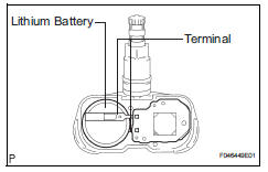
- The battery and base board covered with silicone resin are exposed. While taking out the battery, cut the 2 terminals that connect the battery and the base board.
 Installation
Install tire pressure warning antenna and receiver
Install the receiver with the bolt.
Torque: 7.5 N*m (76 kgf*cm, 66 in.*Lbf)
Connect the connector.
Install inner roof side g ...
 Tire pressure warning ecu
Components
Removal
Disconnect cable from negative battery
terminal
Caution:
Wait at least 90 seconds after disconnecting the
cable from the negative (-) battery terminal to
prevent ai ...
Other materials:
Audio system types
Vehicles with an entune premium audio with navigation
Refer to the “navigation and multimedia system owner’s
manual”.
Vehicles with an entune audio plus
Refer to the “navigation and multimedia system owner’s
manual”.
Vehicles with an entune audio
Vehicles ...
If a warning light turns
on or a warning buzzer
sounds
Calmly perform the following actions if any of the warning lights
comes on or flashes. If a light comes on or flashes, but then
goes off, this does not necessarily indicate a malfunction in the
system. However, if this continues to occur, have the vehicle
inspected by your toyota dealer.
Stop t ...
Front passenger side satellite sensor bus initialization incomplete
Description
When the center airbag sensor receives signals from the lateral deceleration
sensor, it determines
whether or not the srs should be activated.
Dtc b1648/82 is recorded when a malfunction is detected in the rear airbag
sensor rh circuit.
Wiring diagram
Inspection pr ...
