Toyota RAV4 (XA40) 2013-2018 Service Manual: Torque converter clutch solenoid performance (shift solenoid valve dsl)
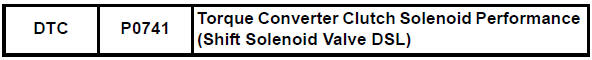
Description
The ecm uses the signals from the throttle position sensor, air-flow meter, turbine (input) speed sensor, intermediate (counter) shaft speed sensor and crankshaft position sensor to monitor the engagement condition of the lock-up clutch.
Then the ecm compares the engagement conditions of the lock-up clutch with the lock-up schedule in the ecm memory to detect mechanical problems of the shift solenoid valve dsl, valve body and torque converter clutch.
Monitor description
Torque converter lock-up is controlled by the ecm based on the speed sensor (nt), speed sensor (nc), engine rpm, engine load, engine temperature, vehicle speed, transmission temperature and gear selection.
The ecm determines the lock-up status of the torque converter by comparing the engine rpm (ne) to the input turbine rpm (nt). The ecm calculates the actual transmission gear by comparing input turbine rpm control voltage to counter gear rpm (nc). When conditions are appropriate, the ecm requests "lock-up" by applying control voltage to the shift solenoid valve dsl. When the dsl is turned on, it applies pressure to the lock-up relay valve and locks the torque converter clutch.
If the ecm detects no lock-up after lock-up has been requested or if it detects lock-up when it is not requested, the ecm interprets this as a fault in the shift solenoid valve dsl or lock-up system performance.
The ecm will illuminate the mil and store the dtc.
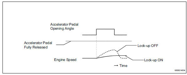
Example:
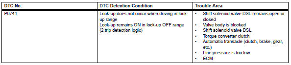
When any of the following is met, the system judges it as a malfunction.
- There is a difference in rotation between the input side (engine speed)
and output side (input turbine
speed) of the torque converter when the ecm commands lock-up.
(Engine speed is at least 100 rpm greater than input turbine speed.)
- There is no difference in rotation between the input side (engine speed)
and output side (input turbine
speed) of the torque converter when the ecm commands lock-up off.
(The difference between engine speed and input turbine speed is less than 35 rpm.)
Monitor strategy
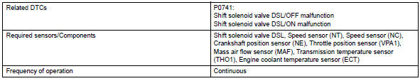
Typical enabling conditions
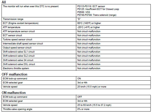
Typical malfunction thresholds
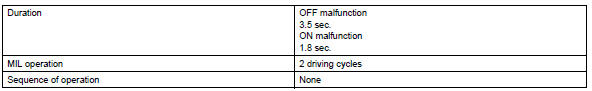
Either of the following conditions is met: off malfunction or on malfunction
Off malfunction![]()
On malfunction
2 Detections are necessary per driving cycle:
1St detection: temporary flag on
2Nd detection: pending fault code on
Vehicle speed must be under 10 km/h (6.2 Mph) once before 2nd detection
![]()
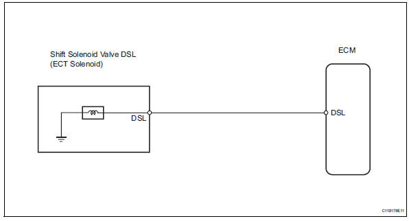
Wiring diagram
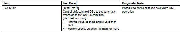
Inspection procedure
Hint:
Performing the intelligent tester's active test allows relay, vsv, actuator and other items to be operated without removing any parts. Performing the active test early in troubleshooting is one way to save time.
The data list can be displayed during the active test.
- Warm up the engine.
- Turn the ignition switch off.
- Connect the intelligent tester to the can vim. Then connect the can vim to the dlc3.
- Turn the ignition switch on and turn the tester on.
- Enter the following menus: diagnosis / enhanced obd ii / active test.
- Follow the instructions on the tester and read the active test.
Hint:
- This test can be conducted when the vehicle speed is 60 km/h (36 mph) or more.
- This test can be conducted in the 3rd or o/d gear
- Lightly depress the accelerator pedal and check that the engine speed does not change abruptly.
Hint:
- When changing the accelerator pedal opening angle while driving, if the engine speed does not change, lock-up is on.
- Slowly release the accelerator pedal in order to decelerate. (Do not fully release the pedal as that will close the throttle valve and lock-up may be turned off.)
- Check other dtc output (in addition to dtc p0741)
- Connect the intelligent tester to the can vim. Then connect the can vim to the dlc3.
- Turn the ignition switch on and turn the tester on.
- Enter the following menus: diagnosis / enhanced obd ii / dtc info / current codes.
- Read the dtcs using the tester.
Result 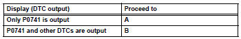
Hint:
If any other codes besides p0741 are output, perform troubleshooting for those dtcs first.


- Inspect transmission wire (shift solenoid valve dsl)
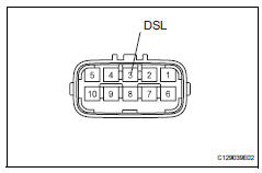
- Disconnect the b27 wire connector.
- Measure the resistance of the transmission wire.
Standard resistance 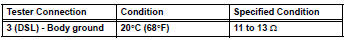


- Check wire harness (transmission wire - ecm)
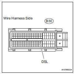
- Disconnect the b30 ecm connector.
- Measure the resistance of the wire harness side connector.
Standard resistance 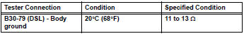

Replace ecm
- Inspect shift solenoid valve dsl
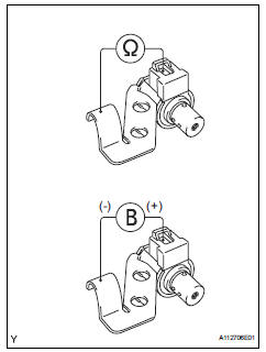
- Remove the shift solenoid valve dsl.
- Measure the resistance of the solenoid valve.
Standard resistance: 11 to 13 ùat 20°c (68°f)
- Connect the battery's positive (+) lead to the terminal of the solenoid valve connector, and the negative (-) lead to the solenoid body. Then check that the valve moves and makes an operating noise.
Ok: valve moves and makes operating noise.


- Check transmission wire
Ok: the connectors and pins are securely installed.
There is no open or short on the wire harness.

- Inspect transmission valve body assembly
- Check the transmission valve body assembly.
Ok: there are no foreign objects on each valve.

- Inspect torque converter clutch assembly
- Check the torque converter clutch assembly (see page ax-153).
Ok: the torque converter clutch operates normally.

Repair automatic transaxle assembly
 Brake switch "B" circuit high
Description
The purpose of this circuit is to prevent the engine from stalling while
driving in the lock-up condition when
the brakes are suddenly applied.
When the brake pedal is depressed ...
 Pressure control solenoid "A " performance (shift solenoid valve sl1)
Description
The ecm uses signals from the vehicle speed sensor to detect the actual gear
position (1st, 2nd, 3rd or
o/d gear).
Then the ecm compares the actual gear with the shift schedule in t ...
Other materials:
Front seats
Adjustment procedure
Manual seat
Seat position adjustment lever
Seatback angle adjustment
lever
Vertical height adjustment
lever (driver’s side only)
Power seat (driver’s side only)
Seat position adjustment switch
Seatback angle adjustment
switch
seat cushion (f ...
On-vehicle inspection
Hint:
When pressing the switch for 0.3 Seconds or less, the roof
glass moves but auto operation does not operate.
Check auto operation
Turn the ignition switch on.
When the roof glass is fully closed, press the slide
open switch for 0.3 Seconds or more. Check that
the roof glass au ...
If the vehicle battery
is discharged
The following procedures may be used to start the engine if the
vehicle’s battery is discharged.
You can also call your toyota dealer or a qualified repair shop.
If you have a set of jumper (or booster) cables and a second vehicle
with a 12-volt battery, you can jump start your vehicle by fo ...
