Toyota RAV4 (XA40) 2013-2018 Service Manual: Brake switch "B" circuit high
![]()
Description
The purpose of this circuit is to prevent the engine from stalling while driving in the lock-up condition when the brakes are suddenly applied.
When the brake pedal is depressed, this switch sends a signal to the ecm. Then the ecm cancels the operation of the lock-up clutch while braking is in progress.
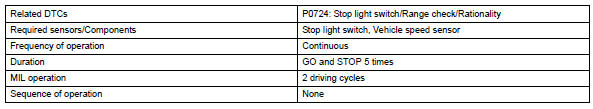
Monitor description
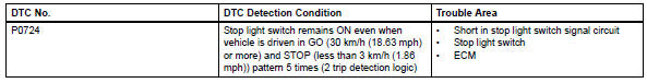
This dtc indicates that the stop light switch remains on. When the stop light switch remains on during go and stop driving, the ecm interprets this as a fault in the stop light switch. Then the mil illuminates and the ecm stores the dtc. The vehicle must go (30 km/h (18.63 Mph) or more) and stop (less than 3 km/h (1.86 Mph)) 5 times for 2 driving cycles in order for the dtc to be output.
Monitor strategy
Typical enabling conditions
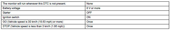
Typical malfunction thresholds
![]()
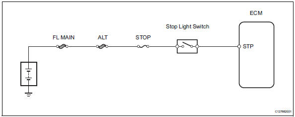
Wiring diagram
Inspection procedure
Hint:
Using the intelligent tester's data list allows switch, sensor, actuator and other item values to be read without removing any parts. Reading the data list early in troubleshooting is one way to save time.
Notice:
In the table below, the values listed under "normal condition" are reference values. Do not depend solely on these reference values when deciding whether a part is faulty or not.
- Warm up the engine.
- Turn the ignition switch off.
- Connect the intelligent tester to the can vim. Then connect the can vim to the dlc3.
- Turn the ignition switch on and turn the tester on.
- Enter the following menus: diagnosis / enhanced obd ii / data list.
- Follow the instructions on the tester and read the data list.
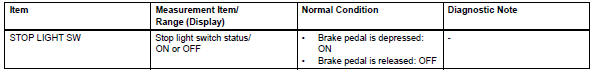
- Inspect stop light switch
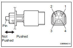
- Remove the a3 stop light switch.
- Measure the resistance of the switch.
Standard resistance 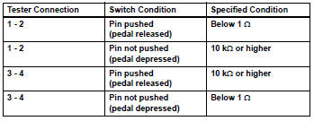


- Check wire harness (ecm - battery)
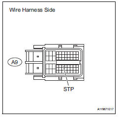
- Measure the voltage of the wire harness side connector.
Standard voltage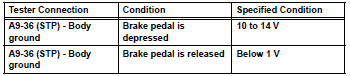

Replace ecm
 Input speed sensor circuit no signal
Description
This sensor detects the rotation speed of the turbine, which shows the input
revolution of the transaxle. By
comparing the input speed signal (nt) with the counter gear speed sens ...
 Torque converter clutch solenoid performance (shift solenoid valve dsl)
Description
The ecm uses the signals from the throttle position sensor, air-flow meter,
turbine (input) speed sensor,
intermediate (counter) shaft speed sensor and crankshaft position sensor t ...
Other materials:
Throttle / pedal position sensor / switch "d" circuit range / performance
Description
Hint:
Refer to dtc p2120 (see page es-282).
Monitor description
When the difference between the output voltages of vpa and vpa2 deviates from
the standard, the ecm
determines that the accelerator pedal position (app) sensor is malfunctioning.
The ecm turns on the mil
and th ...
Vc output circuit
Description
The ecm constantly generates 5 v power from the battery voltages supplied to
the +b (batt) terminal to
operate the microprocessor. The ecm also provides this power to the sensors
through the vc output
circuit.
When the vc circuit is short-circuited, the microprocessor in the ...
Differential oil seal
Components
Replacement
Replace transaxle housing oil seal lh
Drain the automatic transaxle fluid.
Remove the drain plug and gasket, and drain
atf.
Install a new gasket and drain plug.
Torque: 47 n*m (479 kgf*cm, 35 ft.*Lbf)
Remove the front drive shaft lh (see pag ...
