Toyota RAV4 (XA40) 2013-2018 Service Manual: Torque sensor
Description
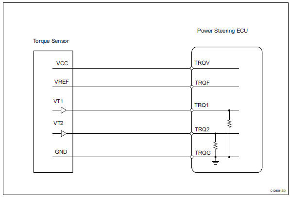
The torque sensor converts the rotation torque input from the steering wheel into electric signals and sends them to the power steering ecu.
Wiring diagram
Inspection procedure
- Check connector connection condition (torque sensor - ecu)
- Check the installation condition of the torque sensor connector.
Ok: torque sensor connector is securely installed to the power steering ecu.
Result 


- Reconfirm dtc
- Reinstall the torque sensor connector.
- Check for dtcs.
Ok:
dtc is not output. 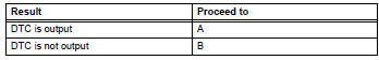

- Inspect torque sensor
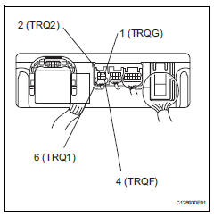
- Turn the ignition switch on.
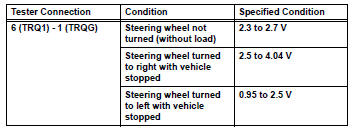
- Measure the voltage of the ecu.
Standard voltage
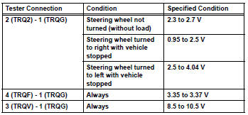

Proceed to next circuit inspection shown in problem symptoms table
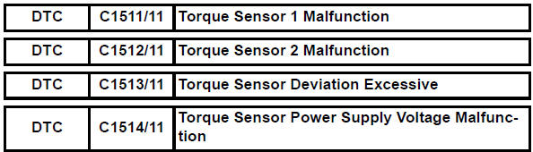
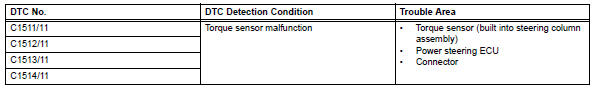
 Diagnostic trouble code chart
Hint:
If any dtcs are displayed during the dtc check, inspect the
circuit listed for these dtcs. For details of each dtc, refer to
the page indicated in the dtc chart.
Hint:
: Warning
...
 Short in motor circuit
Description
The power steering ecu supplies current to the power steering motor through
this circuit.
Inspection procedure
Reconfirm dtc
Check for dtc.
Ok:
dtc is not output.
...
Other materials:
Monitor drive pattern
Test monitor drive pattern for ect
Caution:
Perform this drive pattern on a level surface and
strictly observe the posted speed limits and traffic
laws while driving.
Hint:
Performing this drive pattern is one method to simulate
the ect's malfunction detection conditions.
The dtcs may ...
Operating HomeLink
Press the appropriate
HomeLink button. The
HomeLink indicator light
should turn on.
The status of the opening and
closing of a garage door is
shown by the garage door operation
indicators.
Vehicles with auto anti-glare
inside rear view mirror
Opening
Closing
Vehicles with Digital Rearview
Mirr ...
BluetoothÂź audio/phone
BluetoothÂź audio
The bluetoothÂź audio system enables you to enjoy music played on
a portable digital audio player (portable player) from the vehicle
speakers via wireless communication.
This audio system supports bluetoothÂź, a wireless data system
capable of playing portable audio music wi ...
