Toyota RAV4 (XA40) 2013-2018 Service Manual: Transmitter id
Description
The tire pressure warning valve and transmitter that is installed in the tires and wheels measures the air pressure of the tires. The measured values are transmitted to the tire pressure warning receiver on the body as radio waves and then sent to the tire pressure warning ecu. The ecu compares the measured air pressure values with the air pressure threshold. When the measured air pressure values are less than this threshold, the warning light in the combination meter turns on.
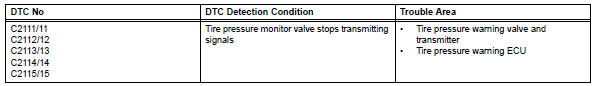
The tire pressure warning ecu stores a dtc when the tire pressure monitor valve stops transmitting signals. At this time, forcibly transmit the signals by releasing the tire pressure rapidly. The stored dtc is cleared when the signal transmission is resumed.
Hint:
It is necessary to perform the procedure to identify the tire pressure monitor valve that is malfunctioning because it cannot be identified by the output dtc.
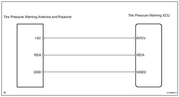
Wiring diagram
Inspection procedure
Notice:
It is necessary to register an id code after replacing the tire pressure warning antenna and receiver and/or the tire pressure warning ecu (see page tw-9).
- Perform forced transmission of transmitter id of all wheels
- Set the pressure of each tire to the specified value.
Standard pressure: 220 kpa (2.2 Kgf/cm2, 32 psi)
- Connect the intelligent tester (with can vim) to the dlc3.
- Turn the ignition switch on.
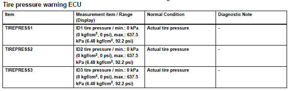
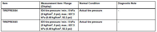
- Select tirepress by following the prompts displayed on the intelligent tester.
- Rapidly release the pressure from each wheel by approximately 40 kpa (0.4 Kgf/cm2, 5.8 Psi) for 30 seconds or more.
- Check that each tire pressure data displayed on the intelligent tester screen changes.
Ok: the tire pressure data displayed on the intelligent tester screen changes with the value of the tire pressure.
Notice:
- It may take up to 1 minute to display the updated tire pressure data.
- When the tirepress data (ids 1 to 5) changes, reset the tire pressure of the tires to the specified value, rotate the tires 90 to 270° and recheck.
- After confirming that the tire pressure data displayed on the intelligent tester screen has changed, set the pressure of each tire to the specified value.
Standard pressure: 220 kpa (2.2 Kgf/cm2, 32 psi)
Hint:
If the tire pressure data displayed on the intelligent tester screen has not changed after rechecking, go to the troubleshooting procedures of dtcs c2121/ 21 to c2125/25 which indicate transmission or reception malfunctions (see page tw-28).

End
 Diagnostic trouble code chart
Hint:
If a trouble code is displayed during the dtc check, check
the circuit listed for that code in the table below. Then
proceed to the appropriate page.
...
 No signal from transmitter id
Description
The tire pressure warning valve and transmitter constantly sends radio waves
to the tire pressure warning
ecu.
Under the following conditions, the tire pressure warning antenna ...
Other materials:
If the vehicle becomes
stuck
Carry out the following procedures if the tires spin or the vehicle
becomes stuck in mud, dirt or snow:
Stop the engine. Set the parking brake and shift the shift lever to p.
Remove the mud, snow or sand from around the stuck tire.
Place wood, stones or some other material to help provide t ...
Throttle actuator control throttle body range / performance
Description
The electronic throttle control system (etcs) is composed of the throttle
actuator, throttle position (tp)
sensor, accelerator pedal position (app) sensor, and ecm. The ecm operates the
throttle actuator to
regulate the throttle valve in response to driver inputs. The tp senso ...
Side airbag sensor
Components
On-vehicle inspection
Check side airbag sensor (vehicle not
involved in collision)
Perform a diagnostic system check (see page rs-
49).
Check side airbag sensor (vehicle involved
in collision and airbag has not deployed)
Perform a diagnostic system check ( ...
