
Toyota RAV4 (XA40) 2013-2018 Service Manual: Engine immobiliser system
Toyota RAV4 (XA40) 2013-2018 Service Manual / Engine immobiliser / Engine immobiliser system
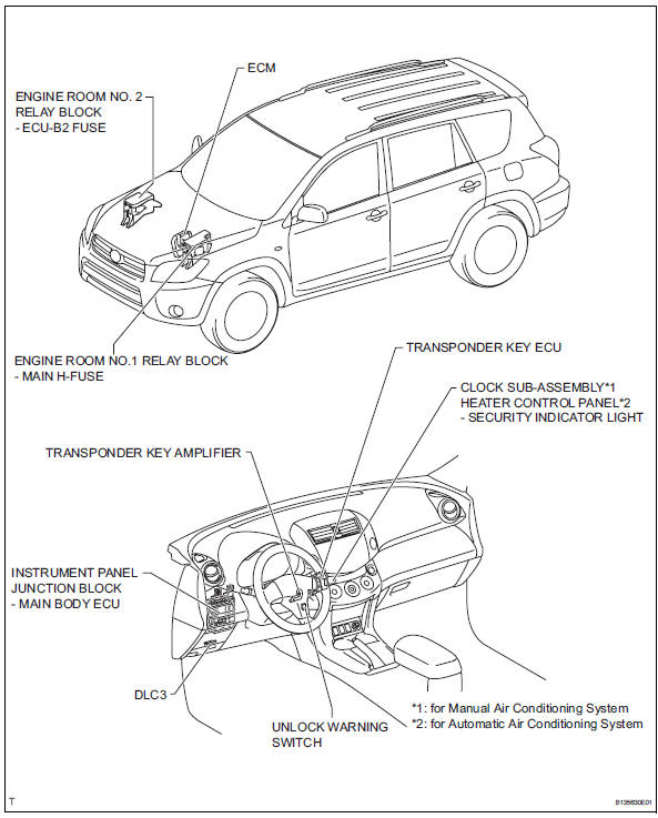
Parts location
System diagram
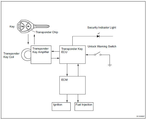
- System description
- How to proceed with troubleshooting
- Registration
- Problem symptoms table
- Terminals of ecu

 System description
Engine immobiliser system description
The engine immobiliser system is designed to prevent
the vehicle from being stolen. This system uses a
transponder key ecu that stores the key codes of
a ...
Other materials:
Starter relay
On-vehicle inspection
Disconnect cable from negative battery
terminal
Caution:
Wait at least 90 seconds after disconnecting the
cable from the negative (-) battery terminal to
prevent airbag and seat belt pretensioner activation.
Remove starter relay
Remove the starter relay fr ...
Parts location
System diagram
...
High pitched horn
Components
Removal
Remove radiator support opening cover
(see page et-4)
Remove front fender liner lh (see page et-4)
Remove front fender liner rh (see page et-4)
Remove front bumper cover (see page et-5)
Remove high pitched horn
Disconnect the horn connector.
Remove t ...
В© 2011-2026 Copyright www.trav4.net
