Toyota RAV4 (XA40) 2013-2018 Service Manual: Active test
Hint:
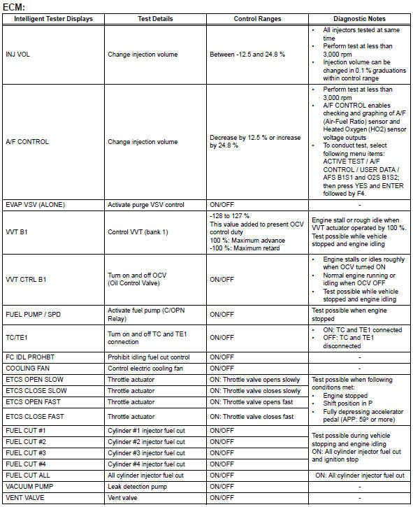
Performing an active test enables components including the relays, vsv (vacuum switching valve) and actuators, to be operated without removing any parts.
The active test can be performed with the intelligent tester. Performing the active test as the first step of troubleshooting is one method of shortening diagnostic time.
Data list can be displayed during active test.
- Connect the intelligent tester to the dlc3.
- Turn the ignition switch on.
- Turn the tester on.
- Select the following menu items: diagnosis / enhanced obd ii / active test.
- Perform the active test by referring to the table below.
Hint:
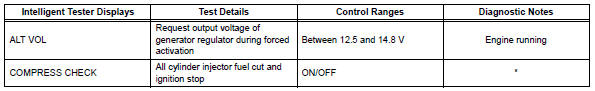
*: When cranking the engine, each cylinder measures the engine rpm.
In this active test, the fuel and ignition of all cylinders is cut, and cranking occurs for approximately 10 seconds. Then, each cylinder measures the engine rpm. If a cylinder's engine rpm is higher than the others, that cylinder's compression pressure is compared to the others, and whether or not the compression pressure is low can be determined.
- Warm up the engine.
- Turn the ignition switch off.
- Connect the intelligent tester to the dlc3.
- Turn the ignition switch on and turn the intelligent tester on.
- Select the following menu items: diagnosis / enhanced obd ii / active test / compress check.
Hint:
If the results are not displayed normally, select the display items from the data list before performing the active test. Select the following menu items: diagnosis / enhanced obd ii / data list / user data / eng speed #1 and eng speed #2, eng speed #3, eng speed #4 (press the yes button to change the eng speed #1 to #4 is yes) and then press the enter button.
- While the engine is not running, press the right or left button to change the compress check to on.
Hint:
After performing the above procedure, the active test's compress check will start. Fuel injection for all cylinders is prohibited, and the each cylinder's engine rpm measurement will enter standby.
- Fully open the throttle.
- Crank the engine for about 10 seconds.
- Monitor the engine speed (eng speed #1 to #4) displayed on the tester.
Hint:
At first, the tester's display will show each cylinder's engine rpm measurement to be extremely high. After approximately 10 seconds of engine cranking, each cylinder's engine rpm measurement will change to the actual engine rpm.
Notice:
- After the active test's compress check is turned on, it will automatically turn off after 255 seconds.
- When the compress check test is off and the engine is cranked, the engine will start.
- If the compress check test needs to be performed after it is turned on and performed once, press exit to return to the active test menu screen. Then perform the compress check test again.
- Use a fully-charged battery.
 Data list
Hint:
By reading the data list displayed on an intelligent
tester, values can be checked, including those of the
switches, sensors, and actuators, without removing any
parts. Reading the data list ...
 System check
Hint:
Performing a system check enables the system,
which consists of multiple actuators, to be operated
without removing any parts. In addition, it can show
whether or not any dtcs are set, and c ...
Other materials:
Functions included in
LTA system
â– Lane departure alert function
When the system determines that the vehicle might depart
from its lane or course*, a warning
is displayed on the multi-information
display, and a warning
buzzer will sound to alert the
driver.
When the warning buzzer sounds,
check the area around your vehicle
and c ...
Emission inspection
and maintenance (i/m)
programs
Some states have vehicle emission inspection programs which
include obd (on board diagnostics) checks. The obd system
monitors the operation of the emission control system.
If the malfunction indicator lamp comes on
The obd system determines that a problem exists somewhere in the
emission contr ...
Vin not programmed or mismatch - ecm / pcm
Description
Dtc p0630 is set when the vehicle identification number (vin) is not stored
in the engine control module
(ecm) or the input vin is incorrect. Input the vin with the intelligent tester.
Monitor strategy
Typical enabling conditions
Typical malfunction thresholds
Com ...
