Toyota RAV4 (XA40) 2013-2018 Service Manual: Data list
Hint:
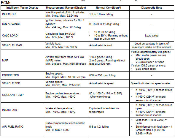
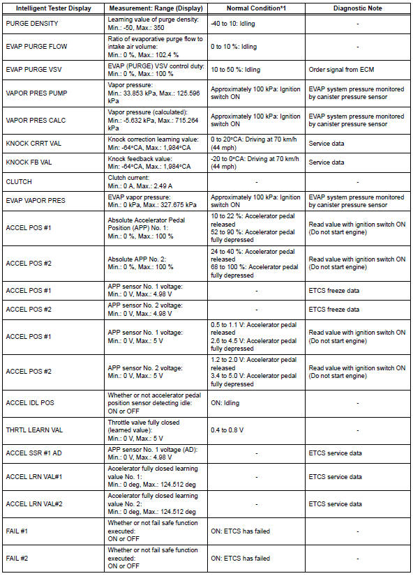
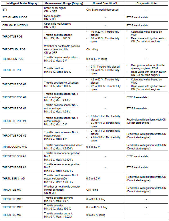
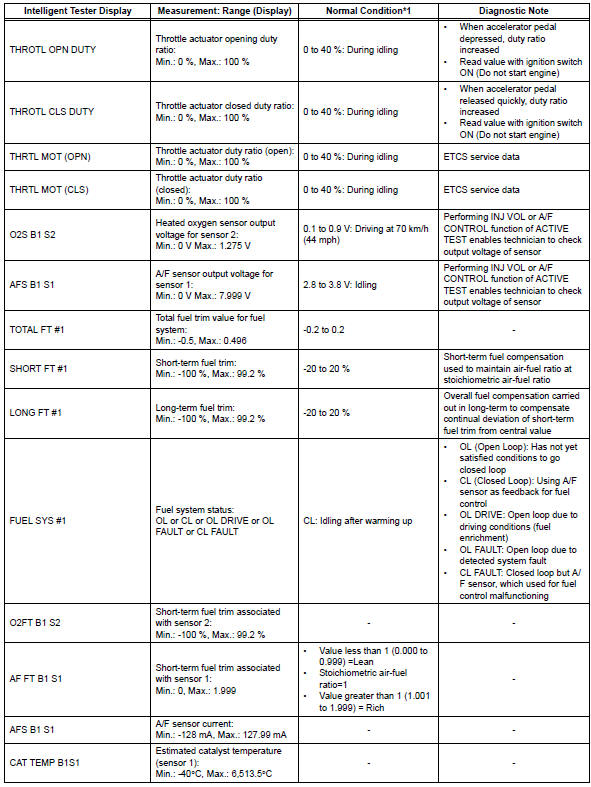
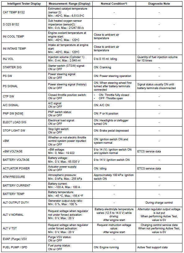
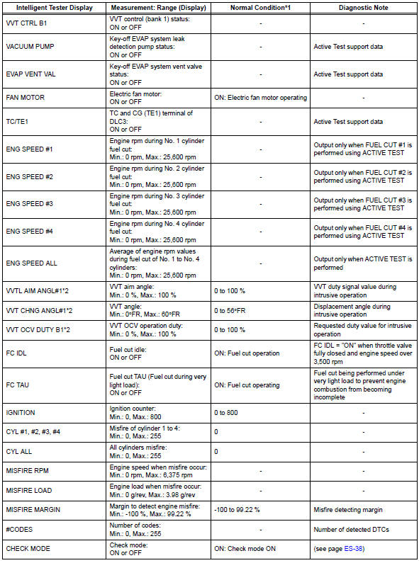
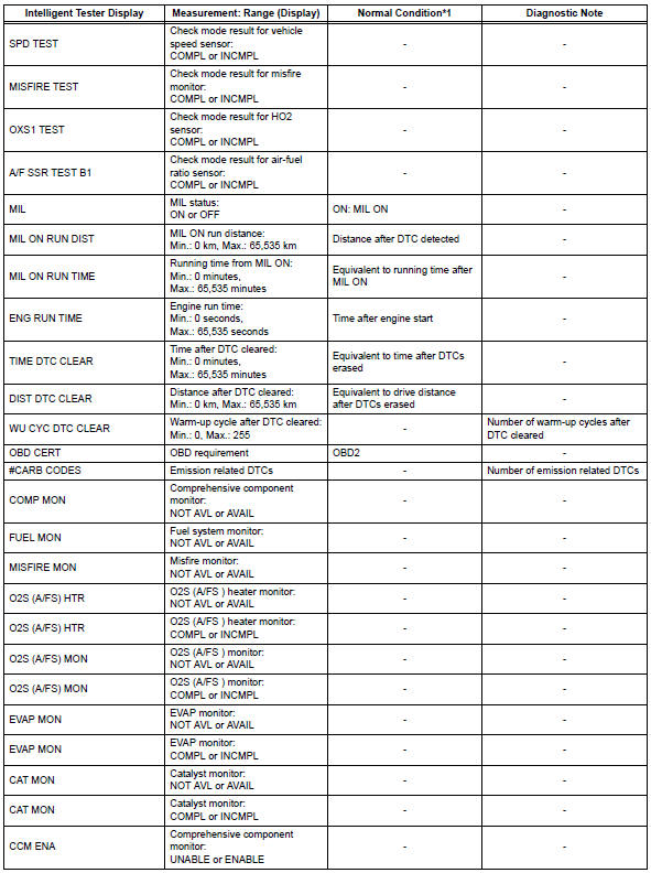
By reading the data list displayed on an intelligent tester, values can be checked, including those of the switches, sensors, and actuators, without removing any parts. Reading the data list as the first step of troubleshooting is one method of shortening diagnostic time.
Notice:
In the table below, the values listed under normal condition are for reference only. Do not depend solely on these values when determining whether or not a part is faulty.
- Warm up the engine.
- Turn the ignition switch off.
- Connect the intelligent tester to the dlc3.
- Turn the ignition switch on.
- Turn the tester on.
- Select the following menu items: diagnosis / enhanced obd ii / data list
- Check the values by referring to the table below.

Hint:
- *1: If no idling conditions are specified, the transmission gear selector lever should be in the n or p position, and the a/c switch and all accessory switches should be off.
- *2: Data list values are only displayed when performing the following active test: vvt b1. For other active tests, the data list value will be 0.

 Active test
Hint:
Performing an active test enables components
including the relays, vsv (vacuum switching valve) and
actuators, to be operated without removing any parts.
The active test can be performed w ...
Other materials:
Cleaning and protecting
the vehicle interior
The following procedures will help protect your vehicle’s interior
and keep it in top condition:
Protecting the vehicle interior
Remove dirt and dust using a vacuum cleaner. Wipe dirty surfaces
with a cloth dampened with lukewarm water.
Cleaning the leather areas
Remove dirt and dust usin ...
Luggage cover (if
equipped)
â– Installing the luggage cover
1. Compress the both ends of
the luggage cover and insert
into the recess to install.
2. Pull out the luggage cover
and hook it onto the anchors.
â– Removing the luggage
cover
1. Release the cover from the
left and right anchors and
allow it to retract.
2. Compre ...
Sruepsptrleaminetnstal restraint system center airbag sensor assembly
Components
On-vehicle inspection
Check center airbag sensor assembly
(vehicle not involved in collision and
airbag not deployed)
Perform a diagnostic system check (see page rs-
49).
Check center airbag sensor assembly
(vehicle involved in collision and airbag
not deplo ...
