Toyota RAV4 (XA40) 2013-2018 Service Manual: Can communication system
Precaution
- Precaution
- Turn the ignition switch off before measuring the resistance of the main wire and the branch wire.
- After the ignition switch is turned off, check that the key reminder warning system and light reminder warning system are not in operation.
- Before measuring the resistance, leave the vehicle for at least 1 minute and do not operate the ignition switch, any switches or doors. If doors need to be opened in order to check connectors, open the doors and leave them open.
Hint:
Operating the ignition switch, any switches or any doors triggers related ecu and sensor communication with the can, which causes resistance variation.
- Steering system handling precautions
- Care must be taken when replacing parts. Incorrect replacement could affect the performance of the steering system and result in hazards when driving.
- Srs airbag system handling precautions
- This vehicle is equipped with an srs (supplemental restraint system) such as the driver airbag and front passenger airbag. Failure to carry out service operations in the correct sequence could cause unexpected srs deployment during servicing and may lead to a serious accident. Before servicing (including installation/removal, inspection and replacement of parts), be sure to read the precautionary notice for the supplemental restraint system (see page rs-1).
- Bus line repair
- After repairing the bus line with solder, wrap the repaired part with vinyl tape (see page in-37).
Notice:
- The canl bus line and canh bus line must be installed together.
- When installing, twist them together.
- Can bus lines are likely to be influenced by noise if the bus lines are not twist together.
- The difference in length between the canl bus line and canh bus line should be less than 100 mm (3.937 In.).
- Leave approximately 80 mm (3.150 In.) Loose in the twisted wires around the connectors.
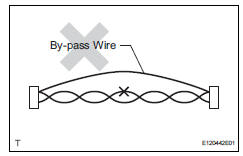
- Do not use bypass wiring between the connectors.
Notice:
The feature of the twisted wire harness will be lost if bypass wiring is used.
- Connector handling
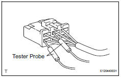
- When inserting tester probes into a connector, insert them from the rear of the connector.
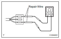
- Use a repair wire to check the connector if it is impossible to check resistance from the rear of the connector.

 Parts location
System diagram
Hint:
The abs and traction actuator (skid control ecu)
detects and stores steering sensor and yaw rate
sensor dtcs and performs dtc communication by
receiving ...
Other materials:
Air inlet control servo motor
Components
Removal
Remove blower assembly
Remove the blower (see page ac-203).
Remove air inlet control servo motor (see
page ac-210)
Inspection
Inspect air inlet control servo motor (for automatic air conditioning
system)
Inspect the servo motor operation. ...
Cargo and luggage
Take notice of the following information about storage precautions,
cargo capacity and load:
Capacity and distribution
Cargo capacity depends on the total weight of the occupants.
(Cargo capacity) = (total load capacity) ƒ{ (total weight of occupants)
Steps for determining correct load l ...
Pressure control solenoid "A " performance (shift solenoid valve sl1)
Description
The ecm uses signals from the vehicle speed sensor to detect the actual gear
position (1st, 2nd, 3rd or
o/d gear).
Then the ecm compares the actual gear with the shift schedule in the ecm memory
to detect mechanical
problems of the shift solenoid valves, valve body or automatic ...
