Toyota RAV4 (XA40) 2013-2018 Service Manual: Disassembly
- Remove no. 1 Side defroster nozzle duct
- Remove the 3 screws and duct.
- Remove no. 2 Side defroster nozzle duct
- Remove the 3 screws and duct.
- Remove no. 1 Heater to register duct
- Remove the screw and duct.
- Remove no. 2 Heater to register duct
- Remove the screw and duct.
- Remove no. 3 Heater to register duct
- Remove the 2 screws and duct.
- Remove no. 1 Instrument panel register assembly
- Remove no. 2 Instrument panel register assembly
- Remove front passenger airbag assembly (see page rs-350)
- Remove automatic light control sensor (for automatic light control system)
- Remove cooler (solar sensor) thermistor (for automatic air conditioning system)
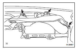
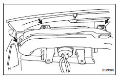
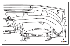
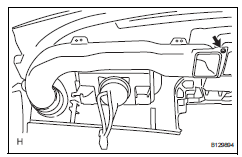
 Removal
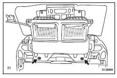
Table of bolt, screw and nut
Hint:
All bolts, screws and nuts relevant to installing and
removing the instrument panel are shown along with
their alphabet codes in the table below.
Di ...
 Reassembly
Install cooler (solar sensor) thermistor
(for automatic air conditioning system)
Install automatic light control sensor
(for automatic light control system)
Install front passenger airbag a ...
Other materials:
Parts location
System diagram
Hint:
The abs and traction actuator (skid control ecu)
detects and stores steering sensor and yaw rate
sensor dtcs and performs dtc communication by
receiving information from the steering sensor and
yaw rate sensor.
The ecm uses the can communication sy ...
Inspection
Inspect water pump assembly
Visually check the drain hole for coolant leakage.
If leakage is found, replace the water pump
assembly.
Turn the pulley, and then check that the water pump
bearing moves smoothly without making a "click"
noise.
If it does not move s ...
Dtc check / clear
Check dtc (using sst (check wire))
Check the dtcs (present trouble code).
Turn the ignition switch on, and wait for
approximately 60 seconds.
Using sst, connect terminals 13(tc) and 4(cg)
of the dlc3.
Sst 09843-18040
Notice:
Connect the terminals to the correct
positio ...
