Toyota RAV4 (XA40) 2013-2018 Service Manual: Dtc check / clear
- Check dtc (using sst (check wire))
- Check the dtcs (present trouble code).
- Turn the ignition switch on, and wait for approximately 60 seconds.
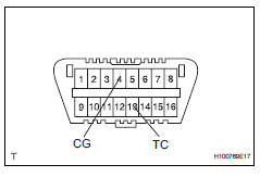
- Using sst, connect terminals 13(tc) and 4(cg) of the dlc3.
Sst 09843-18040
Notice:
Connect the terminals to the correct positions to avoid a malfunction.
- Check the dtcs (past trouble code)
- Using sst, connect terminals tc and 4(cg) of the dlc3.
Sst 09843-18040
Notice:
Connect the terminals to the correct positions to avoid a malfunction.
- Turn the ignition switch on, and wait for approximately 60 seconds.
- Read the dtcs.
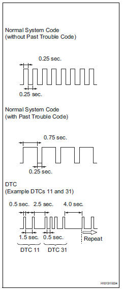
- Read the blinking patterns of the dtcs. As examples, the blinking patterns for the normal system code and dtcs 11 and 31 are shown in the illustration to the left.
- Normal system code indication (without past trouble code): the light blinks twice per second.
- Normal system code indication (with past trouble code): when the past trouble code is stored in the center airbag sensor, the light blinks only once per second.
- Trouble code indication: the first blinking indicates the first dtc. The second blinking occurs after a 1.5 Second pause.
If there is more than 1 code, there will be a 2.5 Second pause between each code. After all codes are shown, there will be a 4.0 Second pause, and then they all will be repeated.
Hint:
- If 2 or more malfunctions are found, the indication begins with the smaller numbered code.
- If dtcs are indicated without connecting the terminals, proceed to the "tc and cg terminal circuit" procedures (see page rs- 233).
- Clear dtc (using sst (check wire))
- Clear the dtcs.
- When the ignition switch is turned off, the dtcs are cleared.
Hint:
Depending on the dtc, the code may not be cleared by turning off the ignition switch. In this case, proceed to the next procedure.
- Using sst, connect terminals 13(13(tc)) and
4(cg) of the dlc3, and then turn the ignition
switch on.
Sst 09843-18040
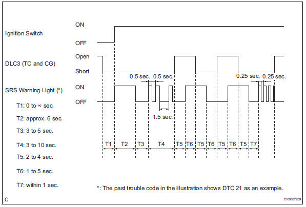
- Disconnect terminal 13(tc) of the dlc3 within 3 to 10 seconds after the dtcs are output, and check if the srs warning light comes on after 3 seconds.
- Within 2 to 4 seconds after the srs warning light comes on, connect terminals 13(tc) and 4(cg) of the dlc3.
- The srs warning light should go off within 2 to 4 seconds after connecting terminals 13(tc) and 4(cg) of the dlc3. Then, disconnect terminal 13(tc) within 2 to 4 seconds after the srs warning light goes off.
- The srs warning light comes on again within 2 to 4 seconds after disconnecting terminal 13(tc). Then, reconnect terminals 13(tc) and 4(cg) within 2 to 4 seconds after the srs warning light comes on.
- Check if the srs warning light goes off within 2
to 4 seconds after connecting terminals 13(tc)
and 4(cg) of the dlc3. Also check if the normal
system code is output within 1 second after the
srs warning light goes off.
If dtcs are not cleared, repeat this procedure until the codes are cleared.
- Check dtc (using intelligent tester)
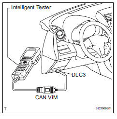
- Connect the intelligent tester (with can vim) to the dlc3.
- Turn the ignition switch on.
- Check the dtcs by following the prompts on the tester screen.
Hint:
Refer to the intelligent tester operator's manual for further details.
- Clear dtc (using intelligent tester)
- Connect the intelligent tester (with can vim) to the dlc3.
- Turn the ignition switch on.
- Clear the dtcs by following the prompts on the tester screen.
Hint:
Refer to the intelligent tester operator's manual for further details.
 Diagnosis system
Description
The center airbag sensor controls the functions of the
supplemental restraint system (srs) on the vehicle.
Data of the srs can be read in the data link connector
3 (dlc3) of the ...
 Check mode procedure
Check mode (signal check)
Connect the intelligent tester (with can vim) to the
dlc3.
Turn the ignition switch on.
Select the "signal check", and continue
checking with t ...
Other materials:
Wheels
If a wheel is bent, cracked or
heavily corroded, it should
be replaced. Otherwise, the
tire may separate from the
wheel or cause a loss of
handling control.
Wheel selection
When replacing wheels, care
should be taken to ensure that
they are equivalent to those
removed in load capacity, diameter,
rim ...
Console box
Lift the lid while pulling up the
lever to release the lock.
When using the console box lid as an armrest (vehicles with slide
function)
Slide the console box lid forward as
needed. Pull the lid forward by holding the
front of the lid.
Caution
Console box adjustment precaution
D ...
Location of the interior lights
Rear interior light
Front interior lights/personal lights
Open tray lights (if equipped)*
Footwell lights (if equipped)*
Front cup holder lights (if equipped)*
*: These lights turn on when a door is unlocked.
When the shift lever is in a position other than P, the brightness of these
ligh ...
