Toyota RAV4 (XA40) 2013-2018 Service Manual: Front wheel alignment
Adjustment
- Inspect tires
- Inspect the tires (see page tw-1).
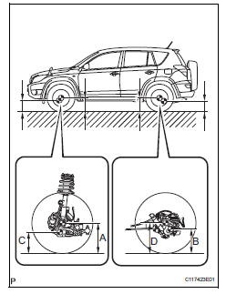
- Measure vehicle height
Notice:
Before inspecting the wheel alignment, adjust the vehicle height to the specification.
- Press down on the vehicle several times to stabilize the suspension, and measure the vehicle height.
- Measure the front vehicle height.
- Measure the distance from the ground to the center of the lower suspension arm front mounting bolt.
- Measure the rear vehicle height.
- Rear measure the distance from the ground to the center of the body side no. 2 Suspension arm mounting bolt.
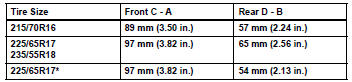
Standard vehicle height (unloaded vehicle)
Hint:
- *: W/ 3rd seat.
- If the vehicle height is not as specified, press down on the vehicle several times to stabilize the suspension. Then measure the vehicle height again.
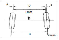
- Inspect toe-in
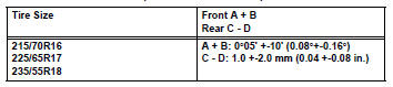
Standard toe-in (unloaded vehicle)
If the toe-in is not as specified, adjust it at the rack ends.
- Adjust toe-in
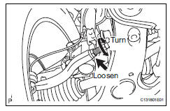
- Remove the boot clips.
- Loosen the tie rod end lock nuts.
- Turn the right and left rack ends by an equal amount to adjust the toe-in to the center value.
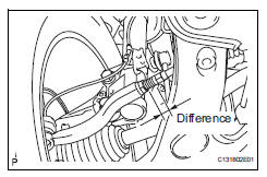
- Make sure that the length of the right and left rack ends are approximately the same.
Standard difference: 1.5 Mm (0.059 In.) Or less
- Tighten the tie rod end lock nuts.
Torque: 55.5 N*m (566 kgf*cm, 41 ft.*Lbf)
- Place the boots on the seats and install the clips.
Hint:
Make sure that the boots are not twisted.
- Inspect wheel angle
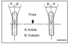
- Turn the steering wheel to the left and right full lock positions, and measure the turning angle.
Standard wheel angle (unloaded vehicle)
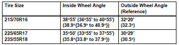
If the angles are not as specified, check and adjust the right and left rack end lengths.
- Inspect camber, caster and steering axis inclination
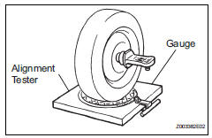
- Install the camber-caster-kingpin gauge or place the front wheels on the center of the wheel alignment tester.
- Inspect the camber, caster and steering axis inclination.
Standard camber inclination (unloaded vehicle)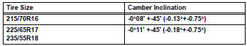
Standard caster inclination (unloaded vehicle)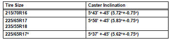
Hint:
*: W/ 3rd seat
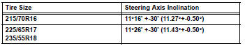
Standard steering axis inclination (unloaded vehicle)
- Adjust camber and caster
Notice:
After the camber has been adjusted, inspect the toein.
- Remove the front wheel.
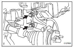
- Remove the 2 nuts on the lower side of the shock absorber.
- Coat the threads of the nuts with engine oil.
- Temporarily install the 2 nuts.
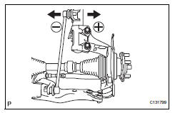
- Adjust the camber by pushing or pulling the lower side of the shock absorber in the direction where the camber adjustment is required.
- Tighten the 2 nuts.
Torque: 240 n*m (2,447 kgf*cm, 177 ft.*Lbf)
- Install the front wheel.
Torque: 103 n*m (1,050 kgf*cm, 76 ft.*Lbf)
- Check the camber.
If the measured value is not within the specified range, calculate the required adjustment amount using the formula below.
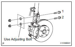
If the camber is not within the specification, estimate how much additional camber adjustment will be required and select the camber adjusting bolt using the following table.
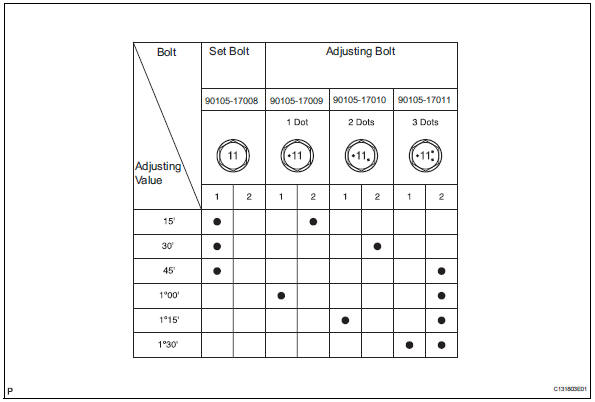
- Repeat the steps mentioned above. When temporarily installing the 2 nuts, replace 1 or 2 selected bolts.
Hint:
Replace 1 bolt at a time when replacing 2 bolts.
 Suspension system
Problem symptoms table
Hint:
Use the table below to help determine the cause of the
problem symptom. The potential causes of the symptoms are
listed in order of probability in the "suspected ...
 Rear wheel alignment
adjustment
Inspect tire
Inspect the tire (see page tw-1).
Measure vehicle height
Measure the vehicle height (see page sp-3).
Inspect toe-in
Standard toe-in
If the ...
Other materials:
Occupant classification ecu malfunction
Description
Dtc b1795 is recorded when a malfunction is detected in the occupant
classification ecu.
Troubleshoot dtc b1771 first when dtc b1771 and b1795 are output simultaneously.
Wiring diagram
Inspection procedure
Check for dtc
Turn the ignition switch on, and wait ...
Installation
Hint:
Use the same procedures for the rh side and lh side.
The procedures listed below are for the lh side.
Install rear door belt moulding assembly
lh
Attach the claws to install the moulding.
Hint:
Confirm that the moulding is firmly installed.
Install rear door tr ...
Mil circuit
Description
The mil (malfunction indicator lamp) is used to indicate vehicle malfunction
detections by the ecm.
When the ignition switch is turned on, power is supplied to the mil circuit, and
the ecm provides the
circuit ground which illuminates the mil.
The mil operation can be checked ...
