Toyota RAV4 (XA40) 2013-2018 Service Manual: Hydraulic test
- Measure line pressure
Notice:
- Perform the test at the normal operating atf temperature: 50 to 80°c (122 to 176°f).
- The line pressure test should always be performed with at least 2 people. One person should observe the condition of the wheels or wheel chocks while the other is performing the test.
- Be careful to prevent sst's hose from interfering with the exhaust pipe.
- This test must be performed after checking and adjusting the engine.
- Perform the test with the a/c off.
- When conducting the stall test, do not continue for more than 10 seconds.
- Warm up the atf.
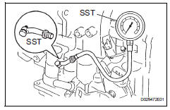
- Remove the test plug on the transaxle case center right side and connect sst.
Sst 09992-00095 (09992-00231, 09992-00271)
- Fully apply the parking brake and chock the 4 wheels.
- Start the engine and check the idling speed.
- Keep your left foot firmly on the brake pedal and move the shift lever to d.
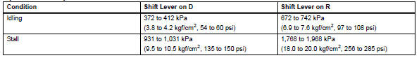
- Measure the line pressure when the engine is idling.
- Depress the accelerator pedal as much as possible with your right foot. Quickly read the highest line pressure reading when the engine speed reaches stall speed.
- Perform the measure line pressure test again with the shift lever on r.
Specified line pressure:
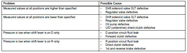
Evaluation:
 Mechanical system tests
Stall speed test
Hint:
This test is to check the overall performance of the
engine and transaxle.
Notice:
Do not perform the stall speed test longer than 5
seconds.
To ensure safety, ...
 Manual shifting test
Manual shifting test
Hint:
Through this test, it can be determined whether the
trouble occurs in the electrical circuit or if it is a
mechanical problem in the transaxle.
If any abnorm ...
Other materials:
Headlight (hi-beam) circuit
Description
The body ecu controls the headlight relay, no. 2 Daytime running light relay
(marking: drl no. 2) And
no. 4 Daytime running light relay (marking: drl no. 4).
Wiring diagram
Inspection procedure
Perform active test by intelligent tester
Connect the intelligent test ...
Installation
Install throttle body
Install a new gasket onto the intake manifold.
Install the throttle body and fuel pipe clamp with the
4 bolts.
Torque: 30 n*m (305 kgf*cm, 22 ft.*Lbf)
Connect the fuel tube into the clamp.
Connect the wire harness clamp.
Connect the throttle posi ...
Operation flow
Hint:
Perform troubleshooting in accordance with the
procedures below. The following is an outline of basic
troubleshooting procedures. Confirm the troubleshooting
procedures for the circuit you are working on before
beginning troubleshooting.
Ask
the customer about the conditions and en ...
