Toyota RAV4 (XA40) 2013-2018 Service Manual: Check mode procedure
- Description
- Check mode has a higher sensitivity to malfunctions and can detect malfunctions that normal mode cannot detect. Check mode can also detect all the malfunctions that normal mode can detect. In check mode, dtcs are detected with 1 trip detection logic.
- Check mode procedure
- Make sure that the following conditions below are met:
- Battery positive voltage 11 v or more
- Throttle valve fully closed
- Transaxle in the p or n position
- A/c off
- Turn the ignition switch off.
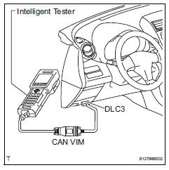
- Connect the intelligent tester to the can vim. Then connect the can vim to the dlc3.
- Turn the ignition switch on and turn the tester on.
- Enter the following menus: diagnosis / enhanced obd ii / check mode.
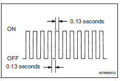
- Change the ecm to check mode. Make sure the mil flashes as shown in the illustration.
Notice:
All dtcs and freeze frame data recorded will be erased if: 1) the intelligent tester is used to change the ecm from normal mode to check mode or vice versa; or 2) during check mode, the ignition switch is turned from on to acc or off.
Before check mode, make notes of the dtcs and freeze frame data.
- Start the engine. The mil should turn off after the engine starts.
- Perform "monitor drive pattern" for the ect
test (see page ax-19).
(Or, simulate the conditions of the malfunction described by the customer.)
- After simulating the malfunction conditions, use the tester to check the dtc and freeze frame data.
 Dtc check / clear
Check dtc
Dtcs which are stored in the ecm can be displayed
with the intelligent tester.
The intelligent tester can display pending dtcs and
current dtcs. Some dtcs are not stored ...
 Fail-safe chart
Fail-safe chart
This function minimizes the loss of the ect functions
when a malfunction occurs in a sensor or solenoid.
Automatic transmission fluid (atf) temperature
sensor:
when the ...
Other materials:
Air fuel ratio sensor
Components
On-vehicle inspection
Check air fuel ratio compensation system
Connect the intelligent tester to the dlc3.
Turn the ignition switch on.
Select the following menu items: data list / a/fs b1
s1 and o2s b1 s2.
Warm up the a/f sensor with the engine speed at
2,500 ...
Customize parameters
Hint:
The following items can be customized.
Notice:
When the customer requests a change in a function,
first make sure that the function can be customized.
Be sure to make a note of the current settings before
customizing.
When troubleshooting a function, first make sure that
the fu ...
Removal
Discharge refrigerant from
refrigeration system (see page ac-172)
Disconnect cable from negative battery
terminal
Caution:
Wait at least 90 seconds after disconnecting the
cable from the negative (-) battery terminal to
prevent airbag and seat belt pretensioner activation.
Remove ...
