Toyota RAV4 (XA40) 2013-2018 Service Manual: Fail-safe chart
- Fail-safe chart
This function minimizes the loss of the ect functions when a malfunction occurs in a sensor or solenoid.
- Automatic transmission fluid (atf) temperature sensor: when the atf temperature sensor has a malfunction, o/d up-shift is prohibited
- Counter gear speed sensor nc (speed sensor nc): when the counter gear speed sensor has a malfunction, o/d up-shift is prohibited.
- Shift solenoid valve dsl:
when the solenoid valve dsl has a malfunction, the
current to the solenoid valve is stopped.
This stops lock-up control, then fuel economy decreases.
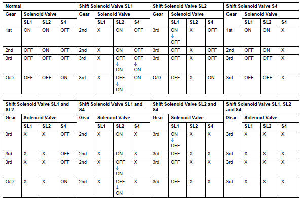
- Shift solenoid valve sl1, sl2 and s4:
if any of the shift solenoid valve circuits develops an
open or short, the ecm turns the other shift solenoid
"on" and "off" in order to shift into the gear
positions shown in the table below.
Manual shifting as shown in the following table must be done. In case of a short circuit, the ecm stops sending the current to the short circuited solenoid.
Even if starting the engine in the fail-safe mode, the gear position remains in the same position.
Hint:
- ?
 : Condition in the normal
operation is shown above the .
. - ?
 : Condition in the
fail-safe mode is shown beneath the .
. - E/b: engine brake.
 Check mode procedure
Description
Check mode has a higher sensitivity to malfunctions
and can detect malfunctions that normal mode
cannot detect. Check mode can also detect all the
malfunctions that normal m ...
 Data list / active test
Read data list
Hint:
Using the intelligent tester's data list allows switch,
sensor, actuator, and other item values to be read
without removing any parts. Reading the data list
early in tro ...
Other materials:
Wireless remote
control/electronic
key battery
Replace the battery with a new one if it is depleted.
You will need the following items:
Flathead screwdriver
Small flathead screwdriver
Lithium battery cr2016 (vehicles without a smart key system), or
cr2032 (vehicles with a smart key system)
Replacing the battery
Vehicles without a ...
Footwell light circuit
Description
The main body ecu receives information regarding the door lock position
switch and ignition switch, and
turns on each foot light.
Wiring diagram
Inspection procedure
Perform active test by intelligent tester (main body ecu)
Connect the intelligent tester (with can vim ...
Power outlet socket
Components
Removal
Disconnect cable from negative battery
terminal
Caution:
Wait at least 90 seconds after disconnecting the
cable from the negative (-) battery terminal to
prevent airbag and seat belt pretensioner activation.
Remove switch base (see page ip-21)
Remove power o ...
