Toyota RAV4 (XA40) 2013-2018 Service Manual: Fuel tank
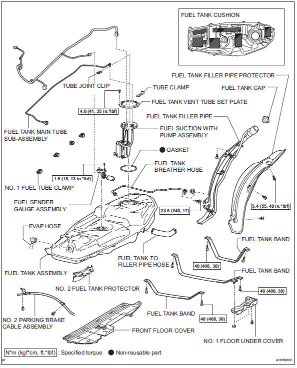
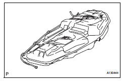
Components
Removal
- Discharge fuel system pressure (see page fu-9)
- Disconnect cable from negative battery terminal
Caution:
Wait at least 90 seconds after disconnecting the cable from the negative (-) battery terminal to prevent airbag and seat belt pretensioner activation.
- Remove fuel tank cap
- Remove front floor cover
- Remove the nut, bolt, 3 clips and floor cover.
- Remove no. 1 Floor under cover
- Remove the 2 nuts, clip and floor under cover.
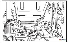
- Disconnect no. 2 Parking brake cable assembly
- Remove the 2 bolts and disconnect the parking brake cable.
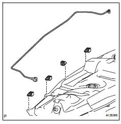
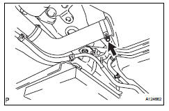
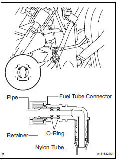
- Disconnect fuel tank main tube subassembly
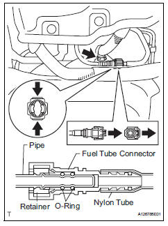
- Pinch and pull the main tube connector to disconnect the connector from the pipe.
Notice:
- Check for foreign matter in the pipe and
around the connector. Clean if necessary.
Foreign matter may damage the o-ring or cause leaks in the seal between the pipe and connector.
- Do not use any tools to separate the pipe and connector.
- Do not forcefully bend or twist the nylon tube.
- Check for foreign matter on the pipe seal surface. Clean if necessary.
- Put the pipe and connector ends in plastic bags to prevent damage and foreign matter contamination.
- If the pipe and connector are stuck together, pinch the connector between your fingers and turn it carefully to disconnect it.
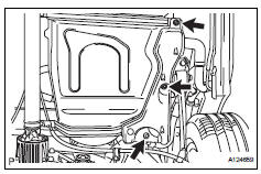
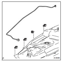
- Disconnect the evap hose from the tank.
- Disconnect fuel tank to filler pipe hose

- Disconnect the filler pipe hose from the fuel tank.
- Disconnect fuel tank breather hose
- Disconnect the breather hose from the fuel tank.
Notice:
- Check for foreign matter in the pipe and
around the connector. Clean if necessary.
Foreign matter may damage the o-ring or cause leaks in the seal between the pipe and connector.
- Do not use any tools to separate the pipe and connector.
- Do not forcefully bend or twist the nylon tube.
- Check for foreign matter on the pipe seal surface. Clean if necessary.
- Put the pipe and connector ends in plastic bags to prevent damage and foreign matter contamination.
- If the pipe and connector are stuck together, pinch the connector between your fingers and turn it carefully to disconnect it.
- Remove fuel tank filler pipe
- Remove the 3 bolts and filler pipe protector.
- Remove the 2 bolts and filler pipe.
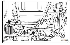
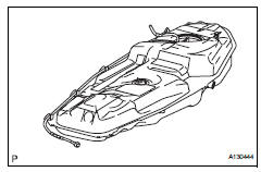
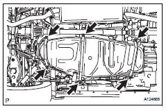
- Remove fuel tank assembly
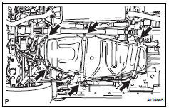
- Set a mission jack underneath the fuel tank.
- Remove the 6 bolts and 3 fuel tank bands.
- Slightly lower the mission jack.
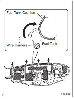
Notice:
Be careful not to cut the wirings.
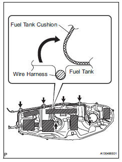
- Fold back approximately half of each cushion rubber so that the wire harness can be detached from the fuel tank in the step below.
- Disconnect the fuel pump connector and sender gauge connector.
Notice:
- Before this procedure, check the connector for dirt, mud or other contamination.
- Do not use any tools in this procedure.
- Detach the wire harness from the 4 clamps and remove the fuel tank.
Disassembly
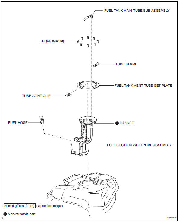
- Remove fuel tank main tube sub-assembly (see page fu-30)
- Remove fuel tank vent tube set plate (see page fu-30)
- Remove fuel suction with pump assembly (see page fu-30)
- Remove fuel tank main tube sub-assembly
- Remove the tube from the fuel tube clamps.
- Remove no. 1 Fuel tube clamp
- Remove the 4 tube clamps from the fuel tank.
- Remove no. 1 Fuel tank cushion
- Remove the 7 fuel tank cushions from the fuel tank.
- Remove fuel sender gauge assembly
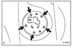
- Remove the 5 screws and sender gauge.
Reassembly
- Install fuel sender gauge assembly
- Install the sender gauge with the 5 bolts.
Torque: 1.5 N*m (15 kgf*cm, 13 in.*Lbf)
- Install no. 1 Fuel tank cushion
- Install 7 new fuel tank cushions onto the fuel tank as shown in the illustration.
- Install no. 1 Fuel tube clamp
- Install the 4 tube clamps to the fuel tank.
- Install fuel tank main tube sub-assembly
- Install the tube with the 4 clips.
- Install fuel suction with pump assembly (see page fu-36)
- Install fuel tank vent tube set plate (see page fu-36)
- Install fuel tank main tube sub-assembly (see page fu-37)
Installation
- Install fuel tank assembly
- Set the fuel tank on a mission jack.
- Lift up the mission jack.
- Fold back the 2 cushion rubbers.
- Connect the fuel pump connector and sender gauge connector to the fuel tank.
Notice:
Be careful not to cut the wirings.
- Attach the wire harness to the 4 clamps.
- Install the 3 fuel tank bands with the 6 bolts.
Torque: 40 n*m (408 kgf*cm, 30 ft.*Lbf)
- Install fuel tank filler pipe
- Install the filler pipe with the 2 bolts.
Torque: 23.5 N*m (240 kgf*cm, 17 ft.*Lbf)
- Install the filler pipe protector with the 3 bolts.
- Connect fuel tank to filler pipe hose
- Connect the filler pipe hose to the fuel tank.
- Connect fuel tank breather hose
- Connect the fuel tank breather hose to the fuel tank.
Notice:
- Before installing the tube connector to the pipe, check the connector for damage and foreign matter.
- Check that the connector and pipe is securely connected by trying to pull them apart.
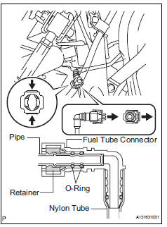
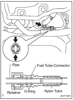
- Connect fuel tank main tube sub-assembly
Notice:
Before installing the tube connector to the pipe, check the connector for damage and foreign matter.
- Connect the main tube connector to the pipe. Push the 2 parts together firmly until a "click" sound is heard.
Notice:
Check that the connector and pipe are securely connected by trying to pull them apart.
- Connect the evap hose to the fuel tank.
- Install no. 1 Floor under cover
- Install the floor cover with the clip and 2 nuts.
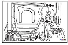
- Install front floor cover
- Install the floor under cover with the 3 clips, bolt and nut.
- Install no. 2 Parking brake cable assembly
- Install the parking brake cable with the 2 bolts.
- Install fuel tank cap
- Connect cable to negative battery terminal
- Check for fuel leaks (see page fu-14)
 Fuel pump
Components
Removal
Remove fuel tank assembly
Remove the fuel tank (see page fu-39).
Remove fuel tank main tube sub-assembly
Remove the joint clip and fuel tank main tube ...

Other materials:
Vacuum switching valve
Components
Removal
Disconnect cable from negative battery
terminal
Caution:
Wait at least 90 seconds after disconnecting the
cable from the negative (-) battery terminal to
prevent airbag and seat belt pretensioner activation.
Remove purge vsv
Disconnect the purge vsv ...
Front seat assembly (for power seat type lh side)
Components
...
On-vehicle inspection
Notice:
Perform the maf meter inspection according to the
procedures below.
Only replace the maf meter when both the long
ft#1 value and maf value in the data list (with the
engine stopped) are not within the normal operating
range.
Inspect mass air flow meter
Perform c ...
