Toyota RAV4 (XA50) 2019-2026 Owners Manual: Garage door opener
The garage door opener can be programmed using the HomeLink to operate garage doors, gates, entry doors, door locks, home lighting systems, security systems, and other devices.
â– HomeLink programming procedure
The programming procedures can also be found at the following URL.
System components
The HomeLink wireless control system in your vehicle has 3 buttons which can be programmed to operate 3 different devices. Refer to the programming methods on the following pages to determine the method which is appropriate for the device.
Vehicles with auto anti-glare inside rear view mirror
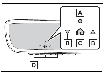
- HomeLink indicator light
- Garage door operation indicators
- HomeLink icon
Illuminates while HomeLink is operating.
- Buttons
Vehicles with Digital Rearview Mirror
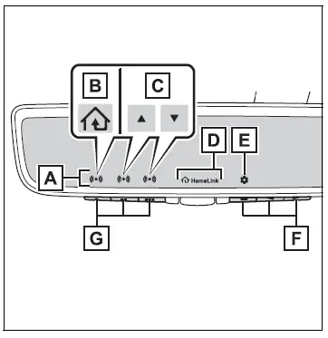
- HomeLink indicator light
Illuminates above each button selected.
- HomeLink icon
- Garage door operation indicators
- HomeLink logo
Appears while HomeLink is operating.
When the HomeLink button is pressed, the logo disappears even while the HomeLink is operating.
- Setting icon
Press the menu button to change the setting.
- Menu buttons
- HomeLink buttons
â– Codes stored in the HomeLink memory
- The registered codes are not erased even if the battery cable is disconnected.
- If learning failed when registering a different code to a HomeLink button that already has a code registered to it, the already registered code will not be erased.
WARNING
â– When programming a garage door or other remote control device
The garage door or other device may operate, so ensure people and objects are out of danger to prevent potential harm.
â– Conforming to federal safety standards
Do not use the HomeLink compatible transceiver with any garage door opener or device that lacks safety stop and reverse features as required by federal safety standards.
This includes any garage door that cannot detect an interfering object. A door or device without these features increases the risk of death or serious injury.
â– When operating or programming HomeLink
Never allow a child to operate or play with the HomeLink buttons.
 Armrest
Fold down the armrest for use.
NOTICE
â– To prevent damage to the
armrest
Do not apply too much load on the
armrest.
Assist grips
An assist grip installed on the
ceiling can be used to support
your b ...
 Programming HomeLink
â– Before programming
HomeLink
During programming, it is possible
that garage doors,
gates, or other devices may
operate. For this reason,
make sure that people and
objects are clear of the
g ...
Other materials:
Definition of terms
Terms
Definition
Monitor description
Description of what ecm monitors and how detects malfunctions
(monitoring purpose and
details).
Related dtcs
Group of diagnostic trouble codes that are output by ecm based on
same malfunction
detection logic.
...
How to proceed with troubleshooting
Hint:
Use these procedures to troubleshoot the supplemental
restraint system.
*: Use the intelligent tester.
Vehicle brought to workshop
Inspect battery voltage*
Standard voltage:
11 to 14 v
If the voltage is below 11 v, recharge or replace the battery
before proceeding.
...
Driver side - side airbag sensor circuit malfunction
Description
The side airbag sensor lh consists of part including the diagnostic circuit
and the lateral deceleration
sensor.
When the center airbag sensor receives signals from the lateral deceleration
sensor, it determines
whether or not the srs should be activated.
Dtc b1620/21 is ...
