Toyota RAV4 (XA40) 2013-2018 Service Manual: Installation
Hint:
- Use the same procedures for the lh side and rh side.
- The procedures listed below are for the lh side.
- A bolt without a torque specification is shown in the standard bolt chart (see page ss-2).
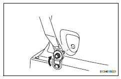
- Install rear no. 1 Seat outer belt assembly lh
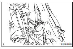
- Align the claws with the seat belt positioning holes, and install the retractor of the seat belt with the 2 bolts as shown in the illustration.
Torque: 8.5 N*m (87 kgf*cm, 75 in.*Lbf) for upper bolt
42 N*m (428 kgf*cm, 31 ft.*Lbf) for lower bolt
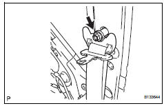
- Connect the shoulder anchor with the bolt.
Torque: 42 n*m (428 kgf*cm, 31 ft.*Lbf)
- Install inner roof side garnish assembly lh (w/ rear no. 2 Seat) (see page ir-52)
- Install rear no. 2 Seat outer belt assembly lh (w/ rear no. 2 Seat)
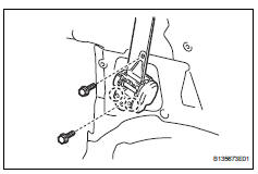
- Align the claws with the seat belt positioning holes and install the retractor of the seat belt with the 2 bolts as shown in the illustration.
Torque: 8.5 N*m (87 kgf*cm, 75 in.*Lbf) for upper bolt
42 N*m (428 kgf*cm, 31 ft.*Lbf) for lower bolt
- Connect the shoulder anchor with the bolt.
Torque: 42 n*m (428 kgf*cm, 31 ft.*Lbf)
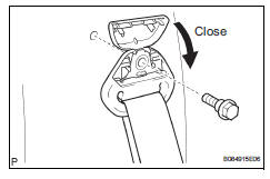
- Close the cover cap.
- Install inner roof side garnish assembly lh (w/o rear no. 2 Seat) (see page ir-51)
- Install deck trim side panel assembly lh (w/ rear no. 2 Seat) (see page ir-53)
- Install deck trim side panel assembly lh (w/ o rear no. 2 Seat) (see page ir-52)
- Connect rear no. 2 Seat outer belt assembly lh (w/ rear no. 2 Seat)
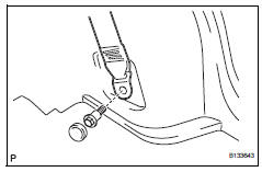
- Connect the seat belt's floor anchor with the bolt.
Torque: 42 n*m (428 kgf*cm, 31 ft.*Lbf)
- Close the cover.
- Connect rear no. 1 Seat outer belt assembly lh
- Connect the seat belt's floor anchor with the bolt.
Torque: 42 n*m (428 kgf*cm, 31 ft.*Lbf)
- Attach the lap belt outer anchor cover.
- Install reclining remote control lever bezel lh (w/o rear no. 2 Seat)
- Install rear floor finish plate (see page ir- 55)
- Install rear no. 1 Floor mat support side plate (see page ir-55)
- Install rear floor no. 3 Board
- Install rear floor no. 2 Board
- Install rear no. 2 Seat assembly lh (w/ rear no. 2 Seat) (see page se-121)
- Install rear no. 2 Seat assembly rh (w/ rear no. 2 Seat) (see page ir-55)
- Install no. 2 Seat leg cover lh (w/ rear no. 2 Seat) (see page se-123)
- Install no. 2 Seat leg cover rh (w/ rear no. 2 Seat) (see page ir-56)
- Install no. 2 Seat hinge cover lh (w/ rear no.
2 Seat) (see page se-123)
- Remove no. 2 Seat hinge cover rh (w/ rear no.
2 Seat) (see page ir-56)
- Install deck board assembly (w/o rear no. 2 Seat)
- Install rear floor no. 1 Board (w/o rear no.
2 Seat)
- Install tonneau cover assembly (w/o rear no. 2 Seat)
- Install package tray trim pocket subassembly (w/o rear no. 2 Seat)
- Install rear door opening trim weatherstrip lh
- Install rear door scuff plate lh (see page ir-57)
- Connect cable to negative battery terminal
 Removal
Hint:
Use the same procedures for the rh side and lh side.
The procedures listed below are for the lh side.
Disconnect cable from negative battery
terminal
Caution:
Wait at least 90 ...
 Rear center seat outer belt assembly
Components
Removal
Caution:
Wait at least 90 seconds after disconnecting the cable
from the negative (-) battery terminal to prevent airbag
and seat be ...
Other materials:
Fog light assembly
Components
Removal
Hint:
Use the same procedures for the rh and lh sides.
The procedures listed below are for the lh side.
Disconnect cable from negative battery terminal
Caution:
Wait at least 90 seconds after disconnecting the
cable from the negative (-) battery terminal to
...
Side airbag sensor
Components
On-vehicle inspection
Check side airbag sensor (vehicle not
involved in collision)
Perform a diagnostic system check (see page rs-
49).
Check side airbag sensor (vehicle involved
in collision and airbag has not deployed)
Perform a diagnostic system check ( ...
Engine coolant temperature circuit range / performance problem
Description
Refer to dtc p0115 (see page es-105).
Monitor description
Engine coolant temperature (ect) sensor cold start monitor
When a cold engine start is performed and then the engine is warmed up, if
the ect sensor value does
not change, it is determined that a malfunction has occ ...
