Toyota RAV4 (XA40) 2013-2018 Service Manual: Installation
- Install generator assembly
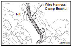
- Confirm that the wire harness of the crankshaft position sensor is secured to the wire harness clamp bracket through the back of the rib of the timing chain cover.
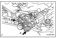
- Install the generator with the 2 bolts.
Torque: 21 n*m (215 kgf*cm, 16 ft.*Lbf) for bolt a 52 n*m (530 kgf*cm, 38 ft.*Lbf) for bolt b
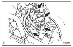
- Install the wire harness clamp.
- Install the wire harness clamp bracket with the bolt.
Torque: 8.4 N*m (85 kgf*cm, 74 in.*Lbf)
- Connect the generator wire with the nut.
Torque: 9.8 N*m (100 kgf*cm, 7 ft.*Lbf)
- Install the terminal cap.
- Connect the generator connector.
- Install fan and generator v belt
- Install the belt (see page em-7).
- Connect cable to negative battery terminal
 Reassembly
Install generator rotor assembly
Install the washer onto the generator rectifier end
frame.
Install the generator rotor onto the generator
rectifier end frame.
Usi ...
 Battery current sensor
On-vehicle inspection
Check battery current sensor assembly
Measure the resistance of the sensor.
Standard resistance
If the result is not as specified, replace the sensor
assembly.
...
Other materials:
Disassembly
Remove idler pulley (see page em-23)
Remove oil dipstick
Remove oil dipstick guide (see page em-57)
Remove manifold stay (see page em-57)
Remove no. 2 Manifold stay (see page em-58)
Remove no. 1 Exhaust manifold heat
insulator (see page em-58)
Remove exhaust manifold converter subas ...
No signal from transmitter id
Description
The tire pressure warning valve and transmitter constantly sends radio waves
to the tire pressure warning
ecu.
Under the following conditions, the tire pressure warning antenna and receiver
is unable to receive the
signals from the tire pressure warning valve and transmitte ...
Engine (ignition) switch
(vehicles without a
smart key system)
Starting the engine
Check that the parking brake is set.
Check that the shift lever is set in p.
Firmly depress the brake pedal.
Turn the engine switch to the ÔÇťstartÔÇŁ position to start the engine.
Changing the engine switch positions
ÔÇťLockÔÇŁ
The steering wheel is locked an ...
