Toyota RAV4 (XA40) 2013-2018 Service Manual: Push switch / key unlock warning switch malfunction

Description
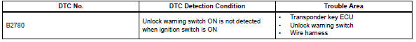
This dtc is output if the transponder key ecu does not detect that the unlock warning switch is on even when the ignition switch is on. Under normal conditions, the unlock warning switch is on when the ignition switch is on.
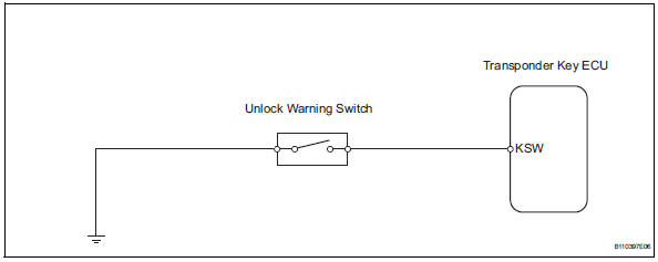
Wiring diagram
Inspection procedure
- Read value of intelligent tester (unlock warning switch)
- Connect the intelligent tester (with can vim) to the dlc3.
- Turn the ignition switch on with a key that cannot start the engine.
- On the intelligent tester, enter the following menus: diagnosis / obd/mobd / immobiliser / data list / key sw. Read the result.
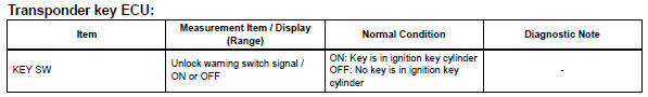
Ok: on (key is in ignition key cylinder) appears on the screen.

- Inspect unlock warning switch assembly
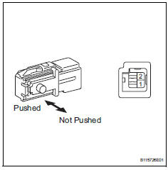
- Remove the unlock warning switch.
- Measure the resistance of the switch.
Standard resistance 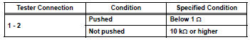

- Check wire harness (unlock warning switch - body ground)
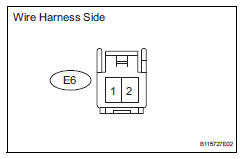
- Disconnect the e6 switch connector.
- Measure the resistance of the wire harness side connector.
Standard resistance 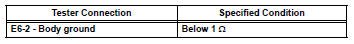

- Check wire harness (unlock warning switch - transponder key ecu)
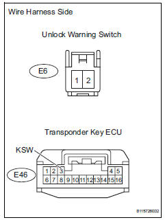
- Disconnect the e6 switch connector.
- Disconnect the e46 ecu connector.
- Measure the resistance of the wire harness side connectors.
Standard resistance 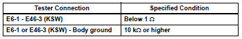

Replace transponder key ecu

 Antenna coil open / short
Description
The transponder key coil receives key code signals from the transponder chip
in the key grip. The coil
built into the transponder key amplifier amplifies the key code signals and
...
Other materials:
Torque converter clutch solenoid performance (shift solenoid valve dsl)
Description
The ecm uses the signals from the throttle position sensor, air-flow meter,
turbine (input) speed sensor,
intermediate (counter) shaft speed sensor and crankshaft position sensor to
monitor the engagement
condition of the lock-up clutch.
Then the ecm compares the engagement ...
Handling of hose clamps
Before removing the hose, check the clamp position
so that it can be reinstalled in the same position.
Replace any deformed or dented clamps with new
ones.
When reusing a hose, attach the clamp on the
clamp track portion of the hose.
For a spring type clamp, you may want to spread ...
Air conditioning control assembly (for automatic air conditioning system)
Components
Removal
Disconnect cable from negative battery
terminal
Notice:
Wait at least 90 seconds after disconnecting the
cable from the negative (-) battery terminal to
prevent airbag and seat belt pretensioner activation.
Remove no. 2 Instrument cluster finish
panel center ...
