Toyota RAV4 (XA40) 2013-2018 Service Manual: Diagnosis system
- Description
- Engine immobiliser system data and diagnostic trouble codes (dtcs) can be read through the vehicle's data link connector 3 (dlc3). In some cases, a malfunction may be occurring in the engine immobiliser system even though the security indicator light is not illuminated. When the system seems to be malfunctioning, use the intelligent tester to check for malfunctions and perform repairs.
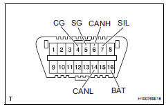
- Check dlc3
The vehicle's ecu uses the iso 15765-4 communication protocol. The terminal arrangement of the dlc3 complies with sae j1962 and matches the iso 15765-4 format.
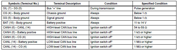
Notice:
*: Before measuring the resistance, leave the vehicle as is for at least 1 minute and do not operate the ignition switch, other switches or doors.
If the result is not as specified, the dlc3 may have a malfunction. Repair or replace the harness and connector.
Hint:
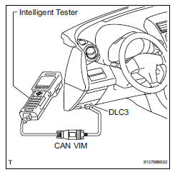
Connect the cable of the intelligent tester (with can vim) to the dlc3, turn the ignition switch on and attempt to use the intelligent tester. If the screen displays unable to connect to vehicle, a problem exists in the vehicle side or the tester side.
If the communication is normal when the tester is connected to another vehicle, inspect the dlc3 on the original vehicle.
If the communication is still not possible when the tester is connected to another vehicle, the problem is probably in the tester itself. Consult the service department listed in the tester's instruction manual.
 Terminals of ecu
Check transponder key amplifier
Disconnect the e5 amplifier connector.
Measure the resistance of the wire harness side
connector.
If the result is not as specified, there may b ...
 Dtc check / clear
Check dtc
Connect the intelligent tester (with can vim) to the
dlc3.
Turn the ignition switch on and turn the intelligent
tester on.
Select the following menu items: diagnosis /
...
Other materials:
Downhill assist control operation switch (test mode dtc)
Description
The downhill assist control switch is connected to the skid control ecu in
the abs and traction
actuator.
Dtc c1379/74 can be detected when the downhill assist control switch sends the
downhill assist control
switch signal or test mode ends. Dtc c1379/74 is output only in t ...
Engine (ignition) switch
(vehicles without smart
key system)
Starting the engine
1. Pull the parking brake switch
to check that the parking
brake is set.
The parking brake indicator will
come on.
2. Check that the shift lever is
set in P.
3. Firmly depress the brake
pedal.
4. Turn the engine switch to
START to start the engine.
‚ñÝIf the engine does not s ...
Fastening the seat belt (for the rear center seat)
Press the plate to release, and
then pull the seat belt.
Push the plate into the buckle in
the order of plate “a” and plate
“b” until a clicking sound is
heard.
Plate “a”, buckle “a”
Plate “b”, buckle “b”
...
