Toyota RAV4 (XA40) 2013-2018 Service Manual: Reassembly
- Install generator rotor assembly
- Install the washer onto the generator rectifier end frame.
- Install the generator rotor onto the generator rectifier end frame.
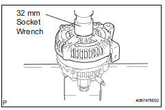
- Using a 32 mm socket wrench and press, slowly push the generator drive end frame onto the generator rectifier end frame.
- Tighten the 4 bolts.
Torque: 5.8 N*m (59 kgf*cm, 51 in.*Lbf)
- Install the cord clip with the bolt.
Torque: 4.6 N*m (47 kgf*cm, 41 in.*Lbf)
- Install generator brush holder assembly
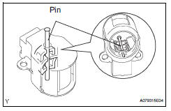
- While pushing the 2 brushes into the generator brush holder, insert a 1.0 Mm (0.039 In.) Pin into the generator brush holder.
- Install the generator brush holder with the 2 screws.
Torque: 1.8 N*m (18 kgf*cm, 16 in.*Lbf)
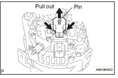
- Pull the pin out of the generator brush holder.
- Install the terminal insulator onto the generator rectifier end frame.
- Install the generator rear end cover with the 3 nuts.
Torque: 4.6 N*m (47 kgf*cm, 41 in.*Lbf)
Install generator pulley with clutch
- Install the pulley by hand.
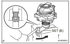
- Install sst to the pulley and vise as shown in the illustration.
Sst 09820-63020
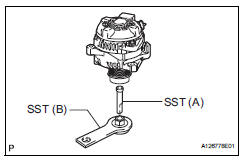
- Turn sst (b) counterclockwise to tighten the pulley.
Torque: 111 n*m (1125 kgf*cm, 81 ft.*Lbf)
- Install a new cap to the pulley.
- Check that the generator pulley rotates smoothly.
 Replacement
Replace generator drive end frame bearing
Remove the 4 screws and bearing retainer.
Using sst and a hammer, tap out the bearing.
Sst 09950-60010 (09951-00250), 09950-70010
(0995 ...
 Installation
Install generator assembly
Confirm that the wire harness of the crankshaft
position sensor is secured to the wire harness
clamp bracket through the back of the rib of the
timing cha ...
Other materials:
Problem symptoms table
Hint:
Use the table below to help determine the cause of the
problem symptom. The potential causes of the symptoms
are listed in order of probability in the "suspected area"
column of the table. Check each symptom by checking the
suspected areas in the order they are listed. Re ...
Installation
Install rear no. 1 Seat assembly lh (w/o rear no. 2 Seat)
Fully tilt the seatback forward.
Place the seat in the cabin.
Notice:
Be careful not to damage the vehicle body.
Connection procedures of seat to lock cable when
reusing seat:
Using a screwdriver, detach the cla ...
Rear bumper
Components
Removal
Remove rear bumper cover
Remove the 9 screws and 7 clips.
Put protective tape under the quarter panel.
Detach the 12 claws and remove the bumper cover.
Remove rear bumper protector
Hint:
When removing the bumper protector, heat the bumper
prot ...
