Toyota RAV4 (XA50) 2019-2026 Owners Manual: Instrument cluster
For the purpose of explanation, the following illustrations display all warning lights and indicators illuminated.
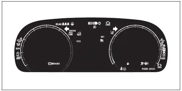
â– With 7-inch multi-information display
The display of the speedometer can be selected from two types, analog or digital.
When analog speedometer is displayed
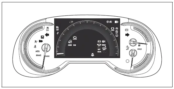
The units used on the meters and some indicators may differ depending on the target region.
When digital speedometer is displayed
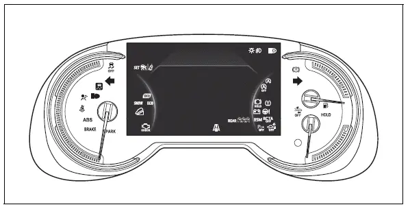
The units used on the meters and some indicators may differ depending on the target region.
â– With 12.3-inch multi-information display
The meter type can be changed on 
of the multi-information display.
Type 1
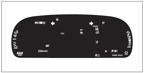
The units used on the meters and some indicators may differ depending on the target region.
Type 2
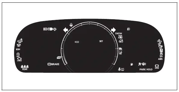
The units used on the meters and some indicators may differ depending on the target region.
Type 3
The units used on the meters and some indicators may differ depending on the target region.

 Warning lights
Warning lights inform the driver
of malfunctions in the indicated
vehicle's systems.
Brake system warning
light*1
Brake system warning
light*1
Brake system warning
light*1
Charging system warning
...
Other materials:
Lost communication with front satellite sensor bus lh
Description
The front airbag sensor lh consists of the diagnostic circuit and the frontal
deceleration sensor.
If the center airbag sensor receives signals from the frontal deceleration
sensor, it determines whether or
not the srs should be activated.
Dtc b1607/84, b1608/84, b1617/84 ...
Push switch / key unlock warning switch malfunction
Description
This dtc is output if the transponder key ecu does not detect that the unlock
warning switch is on even
when the ignition switch is on. Under normal conditions, the unlock warning
switch is on when the
ignition switch is on.
Wiring diagram
Inspection procedure
Re ...
Terminals of ecu (2005/11-2006/01)
Check air conditioning amplifier
Measure the voltage and resistance of the
connectors.
Hint:
Check from the rear of the connector while it is
connected to the air conditioning amplifier.
Using an oscilloscope, check waveform 1.
Compressor and pulley operation signa ...
