
Toyota RAV4 (XA40) 2013-2018 Service Manual: Parts location
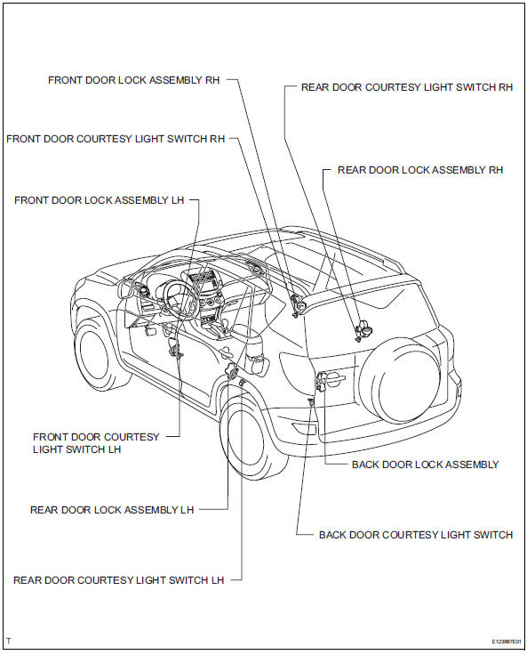
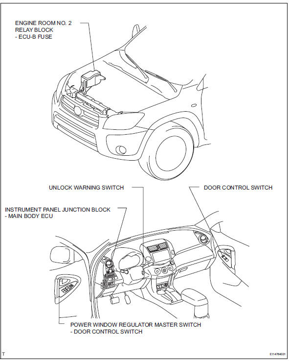
System diagram
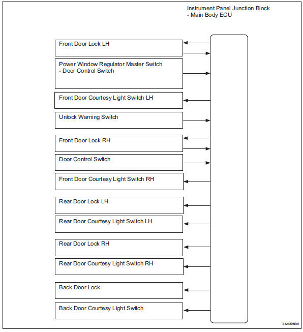

 System description
Power door lock system description
The power door lock system locks / unlocks all
doors with a one-touch operation.
The door control switch of the power window
regulator master swit ...
Other materials:
Evaporative emission control system incorrect purge flow
Dtc summary
Description
The description can be found in the evap (evaporative emission) system (see
page es-335).
Inspection procedure
Refer to the evap system (see page es-340).
Monitor description
The two monitors, key-off and purge flow, are used to detect malfunctions
relating ...
Installation
Caution:
Be sure to read the precautionary notices concerning the
srs airbag system before servicing it (see page rs-1).
Install roof side rail bracket lh
Install the bracket with the 2 bolts.
Torque: 14 n*m (143 kgf*cm, 10 ft.*Lbf)
Install curtain shield airbag assembly lh ...
Using the bluetooth® audio/phone
Audio unit
Bluetooth® connection condition
If “bt� is not displayed, the
bluetooth® audio/phone cannot
be used.
Displays set up menu
Selects items such as menu
and number
Turn: selects an item
Press: inputs the selected item
Off-hook switch
Turns the hands-free sy ...
