Toyota RAV4 (XA40) 2013-2018 Service Manual: Removal
Hint:
- Use the same procedures for the rh side and lh side.
- The procedures listed below are for the rh side.
- Remove no. 2 Seat hinge cover lh
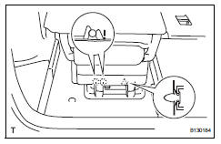
- Fully tilt the seatback forward.
- Attach the 2 claws and clip.
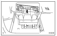
- Pull the hinge cover in the direction indicated by the arrow in the illustration to detach the 2 claws. Then, remove the hinge cover.
- Remove no. 2 Seat leg cover lh
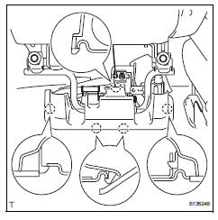
- Using a screwdriver, detach the 5 claws and remove the leg cover.
Hint:
Tape the screwdriver tip before use.
- Remove rear no. 2 Seat assembly
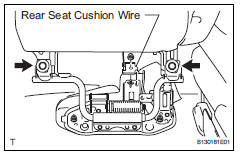
- Remove the nut and rear seat cushion wire.
- Remove the 2 bolts. Then disconnect the seat from the rear no. 2 Seat link.
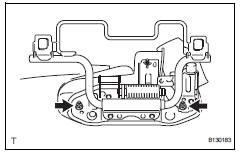
- Remove the 2 nuts and the rear no. 2 Seat link.
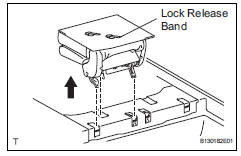
- Pull the lock release band backward and release the 3 seat cushion locks from the lock strikers.
- Lift up and remove the seat.
Notice:
Be careful not to damage the vehicle body,
- Remove rear no. 1 Floor mat support side plate
- Remove no. 2 Seat leg box protector.
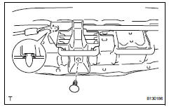
- Using a clip remover, remove the clip.
- Detach the clip. Then remove the protector.
 Rear no. 2 Seat assembly
Components
...
 Disassembly
Hint:
Use the same procedures for the rh side and lh side.
The procedures listed below are for the lh side.
Remove no. 1 Rear seat reclining cover lh
Remove the 2 screws.
Using ...
Other materials:
Terminals of ecu
Check occupant classification ecu
Measure the voltage of the connector.
...
Problem symptoms table
When a "normal" code is output during a dtc check but
the problem is still occurring, use the problem symptoms
table. The suspected areas (circuits or parts) for each
problem symptom are in the table. The suspected areas
are listed in order of probability. A description of each of
the ...
If your vehicle has to
be stopped in an
emergency
Only in an emergency, such as if it becomes impossible to stop
the vehicle in the normal way, stop the vehicle using the following
procedure:
Steadily step on the brake pedal with both feet and firmly depress it.
Do not pump the brake pedal repeatedly as this will increase the effort
req ...
