
Toyota RAV4 (XA40) 2013-2018 Service Manual: Removal
- Disconnect cable from negative battery terminal
Caution:
Wait at least 90 seconds after disconnecting the cable from the negative (-) battery terminal to prevent airbag and seat belt pretensioner activation.
- Disconnect cable from positive battery terminal
- Remove battery clamp
- Remove the bolt and loosen the nut.
- Detach the 2 wire harness clamps.
- Detach the hook of the battery clamp from the battery bracket front, and then remove the battery clamp.
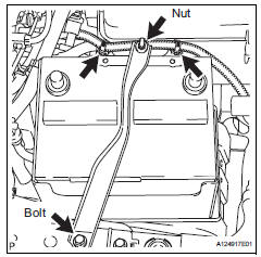
- Remove battery insulator
- Remove battery
- Remove front battery bracket
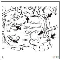
- Detach the 2 wire harness clamps.
- Remove the 4 bolts and bracket front.
- Remove battery bracket reinforcement
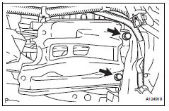
- Remove the 2 bolts and reinforcement bracket.
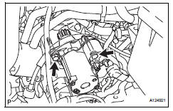
- Remove starter assembly
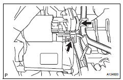
- Disconnect the starter connector.
- Open the terminal cap, remove the nut and disconnect the starter wire.
- Remove the 2 bolts and starter.
 Starter
Components
...
 Disassembly
Remove magnetic switch assembly
Remove the nut and disconnect the lead wire from
the magnetic switch.
Remove the 2 screws holding the magnetic switch
to the starter drive housin ...
Other materials:
Precaution
Handling precaution
When handling the electronic parts:
Avoid any impact to electronic parts such as
ecus and relays. Replace with new ones if
dropped or subjected to a severe blow.
Do not expose any electronic parts to high
temperatures and humidity.
Do not touch the connec ...
System check
Hint:
Performing a system check enables the system,
which consists of multiple actuators, to be operated
without removing any parts. In addition, it can show
whether or not any dtcs are set, and can detect
potential malfunctions in the system. The system
check can be performed with the intelli ...
Tc and cg terminal circuit
Description
Dtc output mode is set by connecting terminals tc and cg of the dlc3.
The dtcs are displayed by blinking the srs warning light.
Hint:
Make sure that dtc b1281 has not been output. If dtc b1281 has been
output, refer to the multiplex
communication system.
When each warning ...
