Toyota RAV4 (XA40) 2013-2018 Service Manual: Disassembly
- Remove magnetic switch assembly
- Remove the nut and disconnect the lead wire from the magnetic switch.
- Remove the 2 screws holding the magnetic switch to the starter drive housing.
- Remove the magnetic switch.
- Remove the return spring and plunger from the starter drive housing.
- Remove starter yoke assembly
- Remove the 2 through-bolts, and pull out the starter yoke together with the commutator end frame.
- Remove the starter yoke from the commutator end frame.
- Remove starter armature plate
- Remove the armature plate from the starter yoke.
- Remove starter commutator end frame cover
- Using a screwdriver, pry out the commutator end frame cover.
- Remove starter armature assembly
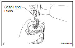
- Using snap ring pliers, remove the snap ring and plate washer.
- Remove the armature from the commutator end frame.
- Remove planetary gear
- Remove the 3 planetary gears from the starter drive housing.
 Removal
Disconnect cable from negative battery
terminal
Caution:
Wait at least 90 seconds after disconnecting the
cable from the negative (-) battery terminal to
prevent airbag and seat belt preten ...
 Inspection
Inspect starter assembly
Notice:
These tests must be performed within 3 to 5 seconds
to avoid burning out the coil.
Perform the pull-in test.
Disconnect the lead wire from terminal c ...
Other materials:
Disassembly
Hint:
When removing the ornament plate and emblem, heat the
radiator grille, ornament plate and emblem using a heat light.
Standard heating temperature
Notice:
Do not heat the emblem base and emblem excessively.
Remove hood to radiator grille seal
Remove the double-side tape.
Deta ...
Using a bluetooth®
phone
The hands-free system is a function that allows you to use your
cellular phone without touching it.
This system supports bluetooth®. Bluetooth® is a wireless data
system that allows the cellular phone to wirelessly connect to
the hands-free system and make/receive calls.
Before making a pho ...
Control module communication bus off
Description
The power steering ecu receives signals from the ecm and the skid control ecu
via the can
communication system.
Hint:
When 2 or more dtcs starting with [u] are output simultaneously, inspect
the connectors and wire
harness of each ecu.
If dtc u0105/41 is output, fi ...
