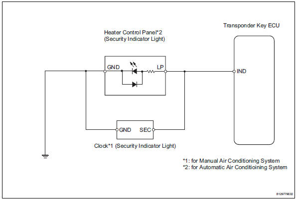
Toyota RAV4 (XA40) 2013-2018 Service Manual: Security indicator light circuit
Description
When the transponder key is registered, the transponder key ecu indicates the key registration condition by lighting up, blinking or turning off the security indicator.
Wiring diagram
Inspection procedure
- Perform active test by intelligent tester (security indicator light)
- Select the active test, use the intelligent tester (with can vim) to generate a command, and then check that the security indicator light operation is normal.

Ok: security indicator light turns on / off.


- Check wire harness (transponder key ecu - security indicator light)
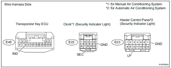
- Disconnect the e46 ecu connector.
- Disconnect the e22*1 or e23*2 light connector.
- Measure the resistance of the wire harness side connectors.
Hint:
*1: For manual air conditioning system
*2: For automatic air conditioning system
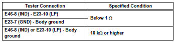
Standard resistance:
for manual air conditioning system 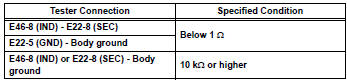
For automatic air conditioning system

- Inspect transponder key ecu (output)
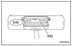
- Remove the transponder key ecu with its connectors still connected.
- Measure the voltage of the ecu.
Standard voltage 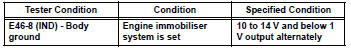


Replace clock sub-assembly (for manual air conditioning system), heater control panel (for automatic air conditioning system)
 Engine immobiliser system malfunction
Description
This dtc is output when one of the following occurs: 1) the ecm detects
errors in its own
communications with the transponder key ecu; 2) the ecm detects errors in the
communicat ...
 Unlock warning switch
Inspection
Inspect unlock warning switch assembly
Measure the resistance of the switch.
Standard resistance
If the result is not as specified, replace the switch
assembly.
Ecu pow ...
Other materials:
Vanity light
Components
Removal
Hint:
Use the same procedures for the rh and lh sides.
The procedures listed below are for the lh side.
Disconnect cable from negative battery
terminal
Caution:
Wait at least 90 seconds after disconnecting the
cable from the negative (-) battery terminal t ...
Throttle / pedal position sensor
Hint:
These dtcs relate to the accelerator pedal position (app) sensor.
Description
Hint:
This etcs (electronic throttle control system) does not use a throttle cable.
The app sensor is mounted on the accelerator pedal bracket and has 2 sensor
circuits: vpa (main) and
vpa2 (sub). This ...
Engine compartment
Engine coolant reservoir
Engine oil filler cap
Battery
Brake fluid reservoir
Fuse box
Radiator
Condenser
Electric cooling fans
Engine oil level dipstick
Washer fluid tank
Engine oil
With the engine at operating temperature and turned off, check the oil
level on the dips ...
