Toyota RAV4 (XA40) 2013-2018 Service Manual: Engine immobiliser system malfunction
![]()
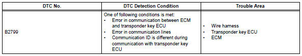
Description
This dtc is output when one of the following occurs: 1) the ecm detects errors in its own communications with the transponder key ecu; 2) the ecm detects errors in the communication lines; or 3) the ecu communication id between the transponder key ecu and ecm is different and an engine start is attempted. Before troubleshooting for this dtc, make sure no transponder key ecu dtcs are present. If present, troubleshoot the transponder key ecu dtcs first.
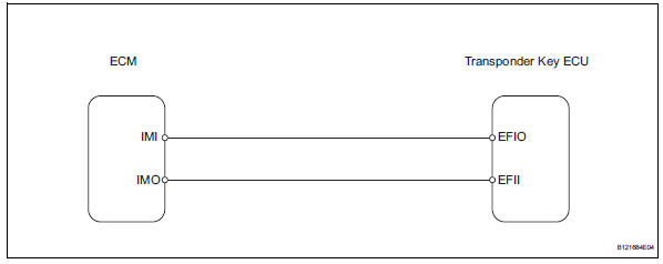
Wiring diagram
Inspection procedure
- Check for dtc
- Delete the dtc (see page ei-18).
- Recheck for dtc.
Ok: b2799 output does not reoccur.


- Check wire harness (transponder key ecu - ecm)
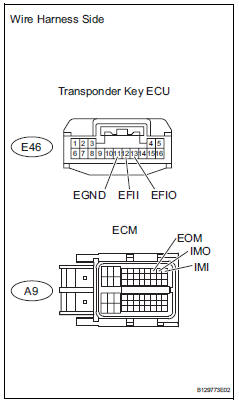
- Disconnect the e46 ecu connector.
- Disconnect the a9 ecm connector.
- Measure the resistance of the wire harness side connectors.
Standard resistance 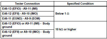

- Check transponder key ecu (operation)
- Temporarily replace the transponder key ecu with a new or normally functioning one.
- Check that then engine starts normally.
Ok: engine starts normally.


End (transponder key ecu is defective)
 Communication malfunction no. 1
Description
This dtc is output when a communication error occurs between the transponder
key amplifier and
transponder key ecu. Some possible reasons for the communication error are: 1) 2
or ...
 Security indicator light circuit
Description
When the transponder key is registered, the transponder key ecu indicates the
key registration condition
by lighting up, blinking or turning off the security indicator.
Wiring diagram ...
Other materials:
Hill-start assist control
When the engine is stopped by
the Stop & Start system when
the vehicle is on an incline,
when the brake pedal is
released, brake force is temporarily
maintained to prevent the
vehicle from rolling backwards
before the engine is restarted
and drive force is generated.
When drive force is generat ...
Wireless charger (if
equipped)
A portable device can be
charged by just placing Qi standard
wireless charge compatible
portable devices according to
the Wireless Power Consortium,
such as smartphones and
mobile batteries, etc., on the
charge area.
This function cannot be used
with portable devices that are
larger than the chargi ...
Preparations to
use wireless
communication
The following can be performed using bluetoothÂź wireless communication:
A portable audio player can be operated and listened to via
audio system
Hands-free phone calls can be made via a cellular phone
In order to use wireless communication, register and connect a
bluetoothÂź device by p ...
