Toyota RAV4 (XA40) 2013-2018 Service Manual: Communication malfunction no. 1
![]()
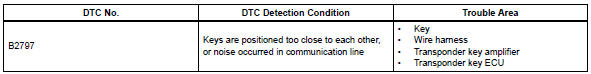
Description
This dtc is output when a communication error occurs between the transponder key amplifier and transponder key ecu. Some possible reasons for the communication error are: 1) 2 or more ignition keys are positioned too close together, or 2) noise is occurring in the communication line.
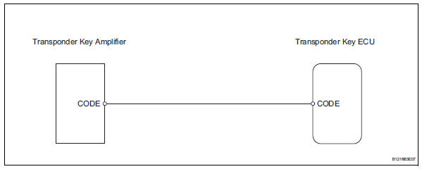
Wiring diagram
Inspection procedure
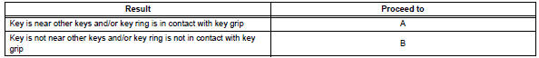
- Check key
- Check if the ignition key being used is near other ignition keys. Also, check if the key ring is in contact with the key grip.
Result:

- Check for dtc
- Separate the keys from each other and / or remove the key ring.
- Clear the dtc (see page ei-18).
- Insert a key into the ignition key cylinder. Remove it.
Repeat for all other keys.
- Check that no dtc is output.
Ok: no dtc is output.

- Check transponder key ecu (noise)
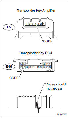
- Using an oscilloscope or the intelligent tester, check for noise in the waveform between the terminals of the e5 amplifier connector and e46 ecu connector.
Ok:
no noise is present (see illustration).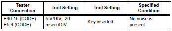

- Check wire harness (transponder key ecu - transponder key amplifier)
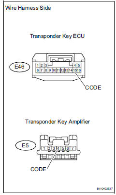
- Disconnect the e46 ecu connector.
- Disconnect the e5 amplifier connector.
- Measure the resistance of the wire harness side connectors.
Standard resistance 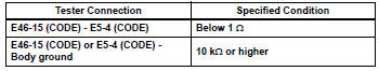

- Check transponder key amplifier (operation)
- Temporarily replacing the transponder key amplifier with a new or normally functioning one.
- Check that the engine starts normally.
Ok: engine starts.

End (transponder key amplifier is defective)
 Communication
Description
When a key is inserted into the ignition key cylinder but no communication
occurs between the key and
transponder key ecu, dtc b2796 is output. When a key is inserted into the
ig ...
 Engine immobiliser system malfunction
Description
This dtc is output when one of the following occurs: 1) the ecm detects
errors in its own
communications with the transponder key ecu; 2) the ecm detects errors in the
communicat ...
Other materials:
Front suspension lower no. 1 Arm
Components
Removal
Remove front wheel
Remove hood sub-assembly
Remove the hood (see page ed-4).
Suspend engine assembly
Install the no. 1 And no. 2 Engine hangers with the
bolts as shown in the illustration.
Torque: 38 n*m (387 kgf*cm, 28 ft.*Lbf)
parts no.
...
Rear window wiper
and washer
Turning the end of the lever turns on the rear window wiper, and pushing
the lever away from you turns on the rear window wiper and
washer.
For the u.S.A.
Intermittent operation
Normal operation
Washer/wiper dual operation
For Canada
Intermittent operation
Normal oper ...
