Toyota RAV4 (XA40) 2013-2018 Service Manual: Terminals of ecm
Hint:
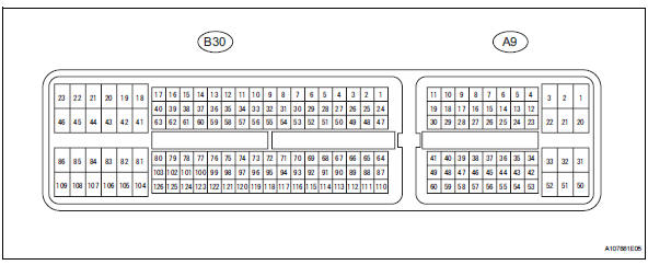
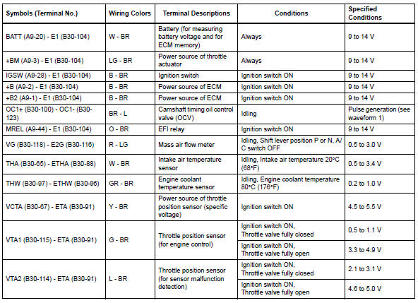
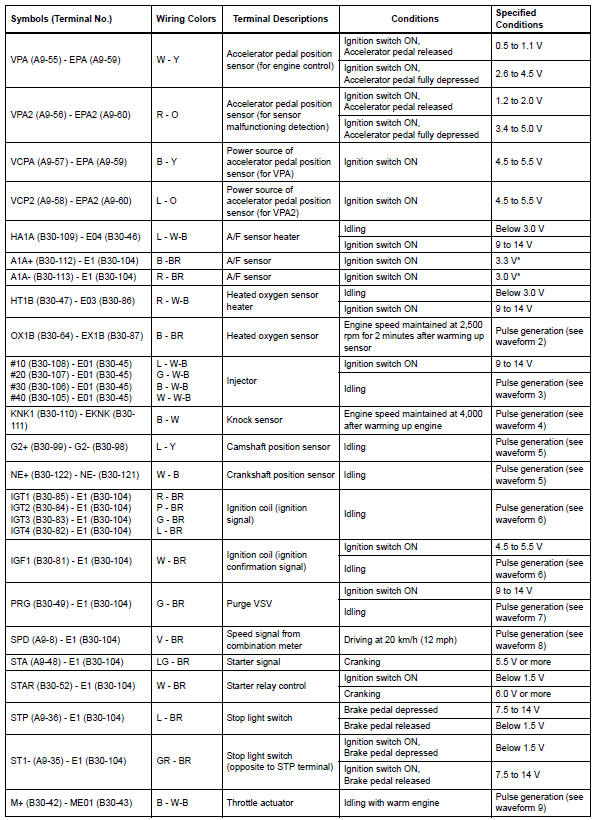
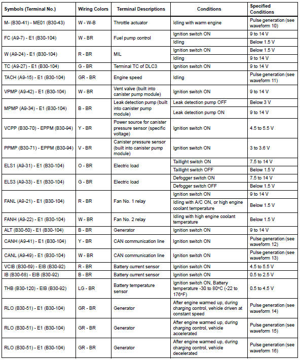
The standard normal voltage between each pair of ecm terminals is shown in the table below. The appropriate conditions for checking each pair of terminals are also indicated. The result of checks should be compared with the standard normal voltage for that pair of terminals, displayed in the specified condition column. The illustration above can be used as a reference to identify the ecm terminal locations.
Hint:
*: The ecm terminal voltage is constant regardless of the output voltage from the sensor.
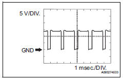
Waveform 1
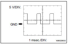 Camshaft
timing oil control valve (ocv) 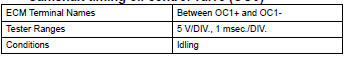
- Waveform 2
 Heated oxygen
sensor 
Hint:
In data list, item o2s b1 s2 shows the ecm input values from the heated oxygen sensor.
- Waveform 3
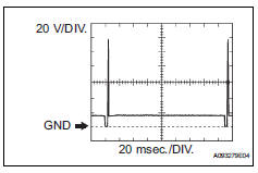 Injector no.
1 (To no. 4) Injection signal 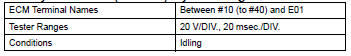
Hint:
The wavelength becomes shorter as the engine rpm increases.
- Waveform 4
 Knock sensor
Hint:
- The wavelength becomes shorter as the engine rpm increases.
- The waveforms and amplitudes displayed differ slightly depending on the vehicle.
- Waveform 5
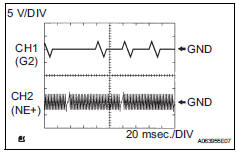 Crankshaft
position sensor and camshaft position
sensor 
Hint:
The wavelength becomes shorter as the engine rpm increases.
- Waveform 6
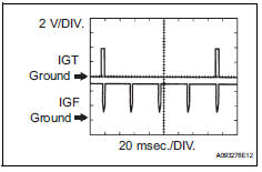 Igniter igt
signal (from ecm to igniter) and igniter
igf signal (from igniter to ecm)
Hint:
The wavelength becomes shorter as the engine rpm increases.
- Waveform 7
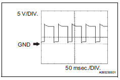 Purge vsv
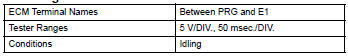
Hint:
If the waveform is not similar to the illustration, check the waveform again after idling for 10 minutes or more.
- Waveform 8
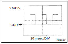 Vehicle speed
signal 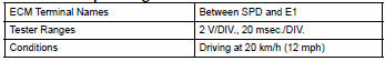
Hint:
The wavelength becomes shorter as the vehicle speed increases.
- Waveform 9
 Throttle
actuator positive terminal 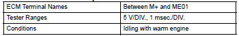
Hint:
The duty ratio varies depending on the throttle actuator operation.
- Waveform 10
 Throttle
actuator negative terminal 
Hint:
The duty ratio varies depending on the throttle actuator operation.
- Waveform 11
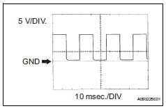 Engine speed
signal 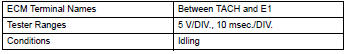
Hint:
The wavelength becomes shorter as the engine rpm increases.
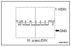
- Waveform 12
 Can
Can
communication signal 
Hint:
The waveform varies depending on the can communication signal.
- Waveform 13
 Can
Can
communication signal 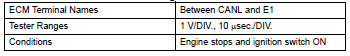
Hint:
The waveform varies depending on the can communication signal.
- Waveform 14
 Generator
Hint:
A constant value is not output, as the duty ratio varies depending on the electrical load and battery condition.
- Waveform 15
 Generator
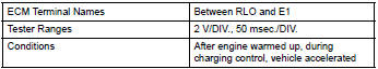
Hint:
A constant value is not output, as the duty ratio varies depending on the electrical load and battery condition.
- Waveform 16
 Generator
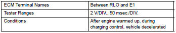
Hint:
A constant value is not output, as the duty ratio varies depending on the electrical load and battery condition.
 Problem symptoms table
Hint:
Use the table below to help determine the cause of the
problem symptom. The potential causes of the symptoms are
listed in order of probability in the "suspected area" column of
th ...
 Diagnosis system
Description
When troubleshooting obd ii (on-board diagnostics)
vehicles, the intelligent tester (complying with sae
j1987) must be connected to the dlc3 (data link
connector 3) of the vehicle ...
Other materials:
Vsc warning light does not come on
Description
Refer to the description of "vsc warning light remains on" (see page bc-139).
Wiring diagram
Refer to the vsc warning light circuit (see page bc-140).
Inspection procedure
Notice:
When replacing the abs and traction actuator, perform the zero point
calibration (see page ...
Air conditioning control assembly (for manual air conditioning system)
Components
Removal
Disconnect cable from negative battery
terminal
Notice:
Wait at least 90 seconds after disconnecting the
cable from the negative (-) battery terminal to
prevent airbag and seat belt pretensioner activation.
Remove no. 2 Instrument cluster finish
panel center ...
Hazard warning switch
Components
Removal
Disconnect cable from negative battery
terminal
Caution:
Wait at least 90 seconds after disconnecting the
cable from the negative (-) battery terminal to
prevent airbag and seat belt pretensioner activation.
Remove no. 1 Instrument cluster finish
panel cente ...
