
Toyota RAV4 (XA40) 2013-2018 Service Manual: Terminals of ecu (2005/11-2006/01)
- Check air conditioning amplifier
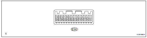
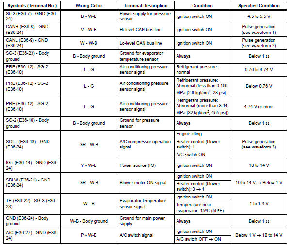
- Measure the voltage and resistance of the connectors.
Hint:
Check from the rear of the connector while it is connected to the air conditioning amplifier.

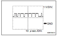
- using an oscilloscope, check waveform 1.
Can communication signal 
Hint:
The waveform varies depending on the can communication signal.
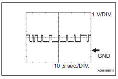
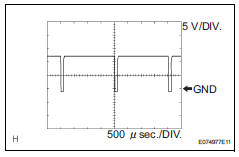
- Using an oscilloscope, check waveform 2.
Can communication signal 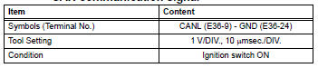
Hint:
The waveform varies depending on the can communication signal.
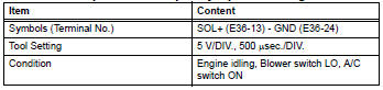
- Using an oscilloscope, check waveform 3.
Compressor and pulley operation signal
 Problem symptoms table (2006/01- )
Hint:
Use the table below to help determine the cause of the
problem symptom. The potential causes of the symptoms
are listed in order of probability in the "suspected area"
colum ...
 Terminals of ecu (2006/01- )
Check air conditioning amplifier
Measure the voltage and resistance of the
connectors.
Hint:
Check from the rear of the connector while it is
connected to the air conditioning ampl ...
Other materials:
Registering a bluetooth®
device
Bluetooth® compatible phones (hfp) and portable audio players
(avp) can be registered simultaneously. You can register up to 5
bluetooth® devices.
How to register a bluetooth® device
Display the “bluetooth* setup� screen.
*: Bluetooth is a registered trademark of bluetooth sig, inc. ...
Warning lights and indicators
The warning lights and indicators on the instrument cluster and
center panel inform the driver of the status of the vehicle’s various
systems.
For the purpose of explanation, the following illustration displays
all warning lights and indicators illuminated.
Instrument cluster
Some indi ...
Differential oil
On-vehicle inspection
Check differential oil
Stop the vehicle on a level surface.
Using a 10 mm socket hexagon wrench, remove the
rear differential filler plug and gasket.
Check that the oil level is between 0 to 5 mm (0 to
0.20 In.) From the bottom lip of the different ...
